Just an update on my 9038q2m progress.
I've started using a TwistedPairAudio IVY-III board to replace the I/V stage and the improvements are immense compared to the original board. I've recently purchased a Khadas Tone Board (a bloody brilliant board) to use as a reference for the work I'm doing on this board and sound difference is a massive leap above that. I'm very impressed!
To recap, I've done the following work:
1) separate PSUs for 5v (LT1963) and +/- 15v feeds (opamp stabilised)
2) AK4137 for upsampling to DSD512
3) separate voltage regs for all 3.3v lines
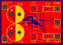
4) ESS reference AVCC circuit
5) Larger 3300uf caps on the AVCC
6) Mains inline filter
All of this sitting in a box file awaiting a suitable case.
I guess the next stages to try are:
1) replacing the crystal
2) what else?
Thanks to Mark for getting me this far!
I've started using a TwistedPairAudio IVY-III board to replace the I/V stage and the improvements are immense compared to the original board. I've recently purchased a Khadas Tone Board (a bloody brilliant board) to use as a reference for the work I'm doing on this board and sound difference is a massive leap above that. I'm very impressed!
To recap, I've done the following work:
1) separate PSUs for 5v (LT1963) and +/- 15v feeds (opamp stabilised)
2) AK4137 for upsampling to DSD512
3) separate voltage regs for all 3.3v lines
4) ESS reference AVCC circuit
5) Larger 3300uf caps on the AVCC
6) Mains inline filter
All of this sitting in a box file awaiting a suitable case.
I guess the next stages to try are:
1) replacing the crystal
2) what else?
Thanks to Mark for getting me this far!
On another note, while ongoing on this dac project, I now have some op amps that have been sitting around. Those LME LME49710 and LME49720s. I have now repurposed an older Assemblage DAC-2 ( Not Benchmark!) for my office PC.
As Mark had reported, these are very sensitive to radiated interference. As per Mark's advice I had now completed a AD797/BUF634 headphone/line stage board for closer listening. With the AD797 it was perfectly quiet with no sign of interference. When the substituted LME40710 was put in, it became sensitive to position and even with my hands over the boards. The AD797/BUF634 had ground planes on both sides.
Finally, I also tried the LME49710s on the Assemblage DAC-2. With the cover off, there was also signs of intereference as well. However when the cover of the enclosure was on, it was gone.
The point is that when using the LME49710/49720 these best be used with proper ground planes as Mark had done and ideally the boards be shielded inside a metal enclosure as well. Experimenting/ audtioning on exposed boards could be misleading. And Yes, the repurposed LME49710s did finally stay inside the Assemblage DAC, it did help open up the somewhat dark sounding 20 year old DAC and surprisingly still not bad sounding when updated. Serendipity?
Last edited:
2) AK4137 for upsampling to DSD512
!
Which upsampling board did you use? I think this could be a summer project.
This one, although not this seller.....
AK4137 DAC SRC Board Digital High-End Audio 786K 32Bit DSD256 DSD IIS Conversion | eBay
Just provides a i2s signal and needs a 5v power supply.
AK4137 DAC SRC Board Digital High-End Audio 786K 32Bit DSD256 DSD IIS Conversion | eBay
Just provides a i2s signal and needs a 5v power supply.
Last edited:
Anyone whether this one which is one of the first ones mentioned
HIFI AK4137 DAC SRC flagship high-end audio 786K 32Bit DSD256 DSD IIS conversion | eBay
or the one recently mentioned by Damiangt3 is better? Or what the differences are? One appears to have a display mountable on a case. Is that really necessary or is it a set and forget thing?
Both appear to allow the XMOS or Amanero directly connect to it without cables.
...the one recently mentioned by Damiangt3 is better? Or what the differences are? One appears to have a display mountable on a case. Is that really necessary or is it a set and forget thing?
The one linked by Damiangt3 appears to be a newer model. The display is different and the clocks look different too (smaller). The display may matter less than the clocks, but hard to say without seeing/hearing one. I just ordered one so I can better comment on it better later.
Anyone whether this one which is one of the first ones mentioned
HIFI AK4137 DAC SRC flagship high-end audio 786K 32Bit DSD256 DSD IIS conversion | eBay
or the one recently mentioned by Damiangt3 is better? Or what the differences are? One appears to have a display mountable on a case. Is that really necessary or is it a set and forget thing?
Both appear to allow the XMOS or Amanero directly connect to it without cables.
I was told the board I've got is a replacement for that one, it's a later revision.
I've started using a TwistedPairAudio IVY-III board to replace the I/V stage and the improvements are immense compared to the original board. I've recently purchased a Khadas Tone Board (a bloody brilliant board) to use as a reference for the work I'm doing on this board and sound difference is a massive leap above that. I'm very impressed!
...
All of this sitting in a box file awaiting a suitable case.
I guess the next stages to try are:
1) replacing the crystal
2) what else?
You are of course very welcome for whatever assistance I am able to provide.
Wondering what you mean you used TP Ivy to replace the I/V stage? Did you mean the original output stage, or the recommended output stage from this thread? If it was the original output stage, it is voltage mode only, so no I/V used for it. Also, sometimes when we talk about the typical 3-opamp output stage topology, we divide it up into I/V stage and differential summing stage.
Anyway, a new clock should help improve sound quality.
If you have not tried it, you may find that film caps on +-15v helps sound quality. Haven't tried it with a TP output stage, so don't know if it would help anything or not.
Of course, learning to program the dac registers is a must if best sound quality is desired. Simply reducing DPLL Bandwidth will help. So will harmonic distortion compensation. So far, only Kaytata has embarked on the first of that part of the journey, that I know of. Maybe when the next person who gets to that stage has questions, Kay could be an additional resource for help. Once he gets a little farther along, perhaps he would be willing to describe how hard it was to do. Knowing about his experience might help other people make a decision if they want to try it.
Its also possible to use RPi to control the dac registers and get the dac sounding very good that way.
Ultimately, some people may wish to try synchronous operation, which can only be done with register programming. Probably best just to take it one step at a time though. When the first dac mod'er gets to the point of wanting to try it would probably be the best time to talk about more of the details.
Speaking of timing, since you mentioned wanting to put the dac in a box, I would certainly recommend using a metal box sufficient to provide good shielding from external RFI/EMI fields. It would be good to leave room in the case for a bit more modding, if possible. There may eventually be a low cost and fairly simple way to assure best sound quality from AK4137. It may also be helpful to add some additional filtering to power supplies and grounds.
Also, overall grounding of all the parts, including the computer (if using other than TOSLINK) and any power amp, can make a very significant difference in sound quality. Maybe that's something we could talk more about too.
Last edited:
...I had now completed a AD797/BUF634 headphone/line stage board for closer listening...
Hi Mike,
How do you find that type of headphone amp? Do you think it is any more revealing than most power amps people likely have?
Well, first off, I am not really a serious headphones type of guy. I absolutely prefer the sense of space and depth and the image in FRONT of me. However, headphones do have their role to play. As a window to more clearly hear what is going on, like a stethoscope. For many where there is no space nor is there the privacy to allow a system to breathe, there is no alternative. Granted the headphones I have are simply Sennheiser HD598s not a serious pair. However, they are revealing enough to discern each type of op amp used as well as power supplies.
Are they more revealing than power amp and speakers. I think in a certain way yes, that is clearly so with no doubt. For me I hear more tonality and expressive changes. However they do not on my system tell me how the image will be presented on speakers.
The other thing is that I am still using power amps that I have built a long time ago. Still state of the art, probably no. What are they? Being a DIY guy, I am using Fully Regulated Leach power amps with Boak Jung regulators. One is the Leach 3 fully sharing a 750VA toroid with separate regulators for each channel. The other is my beast, the Leach Double Barrel fully mono block with each channel and rail using a 500VA toroid so there are 4 of them. All transistors fully matched for gain pairs. Again this one is also fully regulated front end and current gain sections. This one is more transparent than the latter. It also uses your trick of film caps on the rails right on the circuit board for by passing. The Boak regulators are old and depends on caps to flatten the rising HF impedance.--it used a current boosted and voltage lifted via zeners LM340-T as the basis for regulation, preceded by current boosted zeners for preregulation. - Not state of the art today but far superior to just caps. I suspect the magic of the Benchmark AHB2 you are currently using is mainly due to the well regulated power supplies. When I move to a smaller space, I might get one as the power amps I now have are too large.
Getting back to headphone amps. The BUF634/AD797 has a different presentation to an LME49600 buffer with the LME49710. The BUF634 is more polite. The LME49600 has a punchier low end, especially with a LM317/337 standard power supply from which most of them will be powered. It also puts you right in the band or performance. The BUF634 is more detached like a window looking in. I think the preference of one over the other will depend on the individual and the material being listened to.
I have being playing with the BUF634 a bit and found a magical combination to give a tubey sound. Use a TL071 in front of it. It tames all bad recordings and makes everything listenable but boring. The LME49710 is too revealing of all recording flaws in front of it. The AD743 is a contender for the finals, the AD797 is not to my taste, it's tamer than the LME49710 but the best overall so far is as you might have guessed the OPA1611. It just seems to get a good balance of revealing everything without it etching too much of what is there. My BUF634 is being driven by a Sulzer power supply.
The other thing that is different about headphone listening though which seems counter to what I have stated is that they do not appear reveal the difference between different recordings. With speakers and power amps, the difference in perspective and imaging between recording is vast ( and you need to be careful about that aspect in auditioning equipment. You HAVE to listen to the identical source material to make comparisons). On headphones a lot of this is lost. Seems ironic. But one thing I have discovered in this journey is that so much of the old pop music I had been listening to in my youth sounds better on crappy stuff...the crappy recording is revealed on good equipment. Ugh. This is where headphones might be better.
However on good modern jazz vocals that are well recorded, I'll take speakers over headphones any day because the performer is like right in front of me. Yes, I lose the details ( I listened to a 5K top of the line sennheiser system recently) but I prefer the 3D large presence in front of me. Maybe , just maybe I could build a line array system where the low midrange to the top is all AMT type ribbons. With a servo midbass coupler and sub...with a CBT configuration
Last edited:
Register programming
Hi Mark,
I'm hazarding a guess here, might have fried the dac circuit. I notice a couple of times when I remove the connection of the lifted pins of the mcu for the arduino to take over, due to shaky hands the sca and scl lines will touch each other. When it does, the dac board lcd will light up for a brief moment. Now could not get the arduino talking to the dac. Even with the mcu pins connected, the lock light would not come on which it previously does when I connect the xmos board. There is no sound either. I should have made a relay (I have a relay I can use from unused speaker protection board) as you suggested to cleanly takeover and release the mcu.
Also, when connecting arduino to the dac, I connected the sda, scl and gnd lines only. I forgot to connect the vcc line. But it works. So might that be another cause?
Do you think the dac might be fried? If so, I'll order another one. Not a huge problem as they are cheap enough, and I'll have to continue when it arrives. Much of the mods we do being made in another mod board, it will not take much time to modify the dac board again.
I checked the arduino side with the blink program and it works so this side seems to be okay.
Regards,
Kay
You are of course very welcome for whatever assistance I am able to provide. <snip>
Thanks Mark.
My mistake, calling the standard analog output stage an I/V. In my case it was replacing a simple balanced to SE stage that I was using. At present I'm feeding the DACR/RB & L/LB out of the pads before the 6.2k resistors to the IVY-III and then feeding it back in to the board to use the RCA outputs.
I'll have to try film caps, although the size/bulky nature of them might make it tricky! What's the 'sweet spot' with capacitance?
I'll go back and have a read about programming DAC regs. I'm an IT Architect and ex-programmer so that shouldn't be too much of a problem, I can use the Pi and an Arduino board and go from there.
Thanks again!
Hi Kay,
If you had a scope you could see what is going on. That will have to wait though.
I2C is an open collector bus with pullup resistors. Shorting SCL and SDA together shouldn't hurt anything. Shorting them to something else might hurt something. If you short the SCL or SDA pins to another nearby pin that is connected to VCC, then that could ruin the MCU and the Arduino pins so they can't pull down anymore. In that case, you could still talk to the Arduino, but the pins for I2C might be dead. With Some I2C libraries it is possible to use non-standard pins for I2C, not sure about the library I used. Pulling up the dac chip SDA and or SCL pins to 3.3v Vcc should not hurt the dac chip though.
The reason shorting MCU or Arduino pins to Vcc would be destructive is because then there is nothing to limit current when the pins try to pull down. They can't possibly pull down Vcc to ground, they will burn up inside the chip like a fuse first. That's why we need pullup resistors, to limit the maximum current the MCU or Arduino pins have to pull down in order to make I2C bus pulses.
For I2C, we only connect Ground, SDA, and SCL. Not Vcc. The pullup resistors are the only 3.3v shared power source.
If using the translator, it has to be connected to Vcc on both sides, but both sides are isolated in that respect, so each side needs its own power. That is not the case for the MCU and the Arduino, as they each have their own Vcc already.
The only way to properly diagnose damage is with a scope that can watch the I2C lines to see if the MCU and or the Arduino can still pull them down, assuming the pullup resistors are receiving power from the dac board. You should see a stream of pulses on SDA and SCL when an I2C message is sent.
To see if alternate Arduino I2C pins can be used with the existing I2C library, you will have to read the .MD file that describes use of the library. The default I2C pins can work with the hardware timers in the Arduino MCU to control I2C bus pulse timing. If other pins are used for I2C, then software timing has to be used to control the I2C bus pulses. In that case the I2C library would have to include routines that allow alternate use of software-based timing functions.
Also, you might want to be sure you didn't damage the I2C traces under the MCU chip. You should still see 3.3v pull up voltage all the way to the dac chip I2C pins. If a trace got damaged just under the MCU from poking around in there with something, then that could also cause I2C to stop working.
Don't know exactly. Some people have reported some audible improvement with as little as 15uf per +-15v rail, that is to say, a total of 30uf, 15uf from each of the rails to ground. I use closer to 100uf per rail, but that may be a bit more than optimal. What is optimal may also depend on the particular +-15v power supply being used, and also on the particular output stage. You might have to experiment a little to find out.
If you had a scope you could see what is going on. That will have to wait though.
I2C is an open collector bus with pullup resistors. Shorting SCL and SDA together shouldn't hurt anything. Shorting them to something else might hurt something. If you short the SCL or SDA pins to another nearby pin that is connected to VCC, then that could ruin the MCU and the Arduino pins so they can't pull down anymore. In that case, you could still talk to the Arduino, but the pins for I2C might be dead. With Some I2C libraries it is possible to use non-standard pins for I2C, not sure about the library I used. Pulling up the dac chip SDA and or SCL pins to 3.3v Vcc should not hurt the dac chip though.
The reason shorting MCU or Arduino pins to Vcc would be destructive is because then there is nothing to limit current when the pins try to pull down. They can't possibly pull down Vcc to ground, they will burn up inside the chip like a fuse first. That's why we need pullup resistors, to limit the maximum current the MCU or Arduino pins have to pull down in order to make I2C bus pulses.
For I2C, we only connect Ground, SDA, and SCL. Not Vcc. The pullup resistors are the only 3.3v shared power source.
If using the translator, it has to be connected to Vcc on both sides, but both sides are isolated in that respect, so each side needs its own power. That is not the case for the MCU and the Arduino, as they each have their own Vcc already.
The only way to properly diagnose damage is with a scope that can watch the I2C lines to see if the MCU and or the Arduino can still pull them down, assuming the pullup resistors are receiving power from the dac board. You should see a stream of pulses on SDA and SCL when an I2C message is sent.
To see if alternate Arduino I2C pins can be used with the existing I2C library, you will have to read the .MD file that describes use of the library. The default I2C pins can work with the hardware timers in the Arduino MCU to control I2C bus pulse timing. If other pins are used for I2C, then software timing has to be used to control the I2C bus pulses. In that case the I2C library would have to include routines that allow alternate use of software-based timing functions.
Also, you might want to be sure you didn't damage the I2C traces under the MCU chip. You should still see 3.3v pull up voltage all the way to the dac chip I2C pins. If a trace got damaged just under the MCU from poking around in there with something, then that could also cause I2C to stop working.
What's the 'sweet spot' with capacitance?
Don't know exactly. Some people have reported some audible improvement with as little as 15uf per +-15v rail, that is to say, a total of 30uf, 15uf from each of the rails to ground. I use closer to 100uf per rail, but that may be a bit more than optimal. What is optimal may also depend on the particular +-15v power supply being used, and also on the particular output stage. You might have to experiment a little to find out.
Don't know exactly. Some people have reported some audible improvement with as little as 15uf per +-15v rail, that is to say, a total of 30uf, 15uf from each of the rails to ground. I use closer to 100uf per rail, but that may be a bit more than optimal. What is optimal may also depend on the particular +-15v power supply being used, and also on the particular output stage. You might have to experiment a little to find out.
Do they have to be film caps? I have a number of quality poly. caps. that I could use....and there was me saying something about bulky!

Arduino (3.3v version) arriving soon, so I'll have a play with that, I might look at directly controlling from a RPi via Pins 2&3 and use a bit of Python to update the regs.
Looking at the ATtiny24A datasheet, it's pins and 7 & 9 (SDA & SCL) that need to be lifted. Why do they need to be lifted?
Last edited:
(SDA & SCL) that need to be lifted. Why do they need to be lifted?
The MCU on the dac board runs continuously unless you happen to have a board where it ceases activity when J1 and J2 are installed at the same time. Therefore, we may need to disconnect the I2C pins of the dac board MCU. There is some advice about possible approaches in the thread, we can probably find links if it would be helpful.
Then there is the matter of making sure that neither the dac chip nor the arduino is damaged in the case that one device is powered on while the other is powered off. An I2C isolator can be useful for that, or there are other methods.
As to caps, presumably the mechanism by which they can help is that they reduce power supply impedance at higher audio frequencies, maybe up to 100kHz or so. Film caps tend to be low ESR up to reasonably high frequencies for audio, although some have argued that good wide-band high-gain voltage regulators might be as good or better. Nazar regulators have been suggested, which are low cost and easy to build. So far, I don't know that anyone has directly A/B compared some parallel file caps totalling 100uf per rail or so against a 3-transistor Nazar regulator. We can provide some info on the regulators if that might be of interest.
Last edited:
Hi Mark,You should still see 3.3v pull up voltage all the way to the dac chip I2C pins.
Still waiting for the oscilloscope. With the dac powered on, the pull-up resistors are showing 3.3v on the inputs, and .37 & .80 volts on the outputs all the way to the dac pins. Am guessing the traces are fine?
Kay
Hi Kay,
If the MCU and the Aruduino are both disconnected from the I2C lines, then that would suggest the dac chip I2C lines are shorted to ground inside the dac chip.
If you do think the dac chip is the only thing that could be pulling down the I2C lines, then you could try cutting one of the I2C traces between the MCU and the dac chip and see of that lets the pullup resistor pull up that line. If there is still a short to ground after you cut the trace it must be somewhere else other than inside the dac chip. In that case you would have to find the short and remove it, then repair the cut trace with some solder and maybe a little thin strand of wire.
If cutting the trace makes 3.3v return on the load side of the pullup resistor, then the short must be inside the dac chip. Sorry to hear if that is the case.
-Mark
Last edited:
- Home
- Source & Line
- Digital Line Level
- ES9038Q2M Board