AK4499 is up and running using JLsounds USB board for input and MCLK, and Arduino for control. PCM only today, will try to get to DSD tomorrow. 16/44 sounds quite good, very promising, and much easier to get good sound out of than a Sabre dac, IME, so far. This is with the most basic power supply configuration and no differential summing stage. Passively filtered I/V outputs into my HPA balanced input.
Great news.
Maybe we will make an AKM convert out of you!
")
This DAC is what I have been waiting for
- How much was the Eval Board
- Did they do a reasonable job of the layout
- What opamps are they using for I-V
Cheers
Terry
- How much was the Eval Board
$0
Obviously, not the final price. Jam and I guess they would likely have to cost several hundred dollars each.
- Did they do a reasonable job of the layout
Yes, except the I2S inputs are near the middle of the board, but no local mounting points to put a USB board very close to that. The motherboard is 4-layer, but I found a spot where I could drill one hole to make a mounting point close to where I wanted one.
- What opamps are they using for I-V
OPA1611. Sound is likely also very dependent on the 5v Reference Voltage (AVCC-ish) circuits, of which there are four, one for each channel.
EDIT: Also, there is something about the sound of this dac and my ES9028PRO dac that sounds very much the same and not quite right. I am suspicious of the JLsounds I2SoverUSB. Even though it was wired in well and cleanly powered, I could not get ES9028PRO to lock into 128_fs mode with it, so something is not quite right. Plan to try something different for an I2S source soon as I have time, or maybe try a reclocker with JLsounds.
Last edited:
$0
Yes, except the I2S inputs are near the middle of the board, but no local mounting points to put a USB board very close to that. The motherboard is 4-layer, but I found a spot where I could drill one hole to make a mounting point close to where I wanted one.
Sounds good. USB mtg no probs, intricate mechanical jobs are my specialty.
OPA1611. Sound is likely also very dependent on the 5v Reference Voltage (AVCC-ish) circuits, of which there are four, one for each channel.
This doesn't surprise me. 5V AVCC + hellish low internal impedance resistor
array = large current demands.
EDIT: Also, there is something about the sound of this dac and my ES9028PRO dac that sounds very much the same and not quite right. I am suspicious of the JLsounds I2SoverUSB. Even though it was wired in well and cleanly powered, I could not get ES9028PRO to lock into 128_fs mode with it, so something is not quite right.
Check your I2S signal integrity, it should be very clean. Playing with
termination resistor sizes can help. It's worth noting JLsounds MK3, the latest, does re clocking inside what appears to be FPGA and also uses 45 / 49MHz clocks.
The original used 22 / 24MHz clocks and re clocking with flip flops. I feel the
latter is a superior way to do it but not possible if playback of higher sample
rates is desired (and DSD256) Also, low phase noise 22 / 24 MHz clocks are
available.
Plan to try something different for an I2S source soon as I have time, or maybe try a reclocker with JLsounds.
If you re-clock after JLsounds, the max SR will be halved but I think you
should be able to get 384k PCM and DSD256 through.
If I acquire one of these boards, will definitely try an ADA4898 for I-V and AVCC as it has higher current capability and a little more speed.
T
If I acquire one of these boards, will definitely try an ADA4898 for I-V and AVCC as it has higher current capability and a little more speed.
That might not be so easy. Eight OPA1611 are soldered into the dac chip daughterboard, and not a lot of room to work in there. With these low distortion 24-bit dacs I'm not sure speed is as important as low distortion for the I/V opamps. Also, the dac chip has a low current output mode, possibly an easy way to see if current levels affect SQ with OPA1611. For AVCC (an ESS term, not what AKM uses), they have made it easy to try other regulator types.
Will likely have more to say about clocking at some later point.
Last edited:
Hi Mark,
Very happy to hear about your experience with ak4499, can't wait to hear more.
I got JLSounds xmos today, looks similar to the one you have. The connections are very confusing, I could not get it to work at first try. Since I could not see any jumper for enabling the two separate power supplies(Contacted them for advise), I tried with the power option 2 by giving 5v power to pin 12, gnd to 11; got a kind of faulty tone, no music. Grateful if you could share your connections to es9038 board when you have time. I also notice that es9038 board does not have mclk connection(I was trying to connect directly to dac board bypassing ak4137).
Cheers & Regards,
Kay.
Hi Kay,
For unknown reasons the manual for v.III of the I2SoverUSB board is only available by asking for it. They gave me the download link: http://jlsounds.com/uploads/I2SoverUSB v.III.pdf
Also, the board comes with 0-ohm SMD resistors to solder on the back of the USB board to configure it. I have the 0-ohm jumpers on B1, B2, and B3. That makes it produce I2S with both 45-49Mhz clocks and 22-24Mhz clocks. Those clock signals can be used as MCLK. There are two MCLK pins on the USB board, and one with the faster clocks and one with the half-speed clocks. The is a row of I2S output pins and the external +5v input and ground pins. All that can be seen in the document at the above link. The other half of the USB board is by default powered via USB from the computer. That works reasonably well, so only one +5v power connection is needed that you have to supply.
If you want to use the USB board for synchronous clocking of ES9038Q2M, you will need to be able to program the dac registers. If you have started to learn how to do that, then maybe I could give you some more details offline. Besides programming dac registers, you would have to disconnect the existing clock on your dac board and connect up an MCLK signal from the USB board instead. You would not necessarily have to remove the existing clock, you might remove the series damping resistor between the existing clock and the dac chip clock input or something like that and then connect the USB board MCLK on the resistor solder pad that goes into the dac chip.
-Mark
Last edited:
Terry,
My bad. AK4499 daughterboard has four OPA1612, not eight OPA1611. Sorry about that.
The pic I posted shows it pretty clearly if you blow it up to full size. It as back at: https://www.diyaudio.com/forums/digital-line-level/314935-es9038q2m-board-457.html#post5830912
My bad. AK4499 daughterboard has four OPA1612, not eight OPA1611. Sorry about that.
The pic I posted shows it pretty clearly if you blow it up to full size. It as back at: https://www.diyaudio.com/forums/digital-line-level/314935-es9038q2m-board-457.html#post5830912
Last edited:
Terry,
My bad. AK4499 daughterboard has four OPA1612, not eight OPA1611. Sorry about that.
The pic I posted shows it pretty clearly if you blow it up to full size. It as back at: https://www.diyaudio.com/forums/digital-line-level/314935-es9038q2m-board-457.html#post5830912
The board looks pretty good to me. Swapping the OPA's is no problem but you can only do it so many times before damage occurs.
The I2S also looks pretty nicely accessible but probably better to attach it on
the DAC board.
Note the four large electro caps on DAC board, I'm presuming they are for
analog supplies, interesting, they are large!
Are there any components such as bypass caps on underside of DAC board?
Where are DAC AVCC regs? They really should be on DAC board.
WRT current mode only, I'm sure it will happily swing OP voltage but the question is at what distortion / sonic cost?
Overall, it should sound pretty good, they have done a fairly decent job.
I was referred to Arrow Electronics for Eval Board. I get the feeling it will be pricey!
T
Mark,
Thank you very much for the link and info JLsounds i2soverusb. It works as you said by connecting B1,B2 & B3 jumper. And I think I could hear sq improvement compared to the chinese xmos.
Regarding programming the dac register, I tried once with another 8-bit level translator, could not make it work.( not the Sparkfun one, which came damaged. Could not repair it, so re-ordered). Will try again soon. When I succeed to connect to the register, I might try the synchronous route too, if there is sq to be gained.
Cheers,
Kay.
..I might try the synchronous route too, if there is sq to be gained.
I think there is SQ to be gained by doing that, especially with upsampling to DSD in software on a powerful i7 computer. However, plain 16/44 in synchronous mode does not sound better than upsampling to DSD in AK4137 (at its best). I keep thinking about how I might go about making that happen more simply than the way I did it, but it is going to have to wait until I can get back to it.
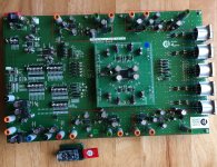
Are there any components such as bypass caps on underside of DAC board?
There are some components including ICs under the mainboard. Haven't looked under the dac daughterboard.
Where are DAC AVCC regs?
Please see areas outlined in red below. One AVCC reg for each channel.
Blue areas are passive differential analog output filters. Caps on underside of board.
Attachments
Hi Mark,
I tried to start arduino i2c programming with DAC_AK-Sketch_1 that you link to.
First I got missing softi2cmaster.h which is easy enough to download the library.
Then I got this error msg: "i2c_init' was not declared in this scope." I could not get beyond
this point. Any suggestions?
Am also not sure if es9038 dac board really stops the i2c connection when J1,J2 jumper is installed. I ran i2c scanner that is included in the softi2cmaster folder which found 126 devices starting from 0x01 to 0x7G.
Regards,
Kay
Hi Kay,
Sorry about that. Recently found out there are now two libraries with the same name. The correct one is at GitHub - felias-fogg/SoftI2CMaster: Software I2C Arduino library ...is that the one you tried?
Regards,
Mark
Sorry about that. Recently found out there are now two libraries with the same name. The correct one is at GitHub - felias-fogg/SoftI2CMaster: Software I2C Arduino library ...is that the one you tried?
Regards,
Mark
Kay,
In that case, just to be sure we are talking about the same thing, don't unzip the library download file. Just go the the Arduino compiler program menu and find the option for importing a zip file. It is under the 'Sketch' menu, then 'include library' then 'add .ZIP library' ...of course, don't do that again if you have already imported the library. The Arduino compile just copies any added libraries to a default user library folder. It is located in the 'Sketchbook' folder which you can change in the Preferences menu, but usually its fine to leave it in the default location.
The Arduino might add another 'include' statement to the program file if you do that with the program open first. If that happens, just delete the added line. If you read the .MD text file in the zip file (Notepadd++ is good freeware for that) it explains the sequence in which things have to be defined, included, and called in the program. If you save a copy of the master zip file and unzip it on the desktop or somewhere handy you will find a folder of example programs. There is a very handy one that can scan I2C bus and find any addresses that answer. Its what I used to find the I2C address of AK4499 on its eval board. The examples also show how to call and use the library functions. If you want you can copy the example folder into the default Arduino 'examples' directory so the examples are convenient to call up if you want to run them or look at how the coding is done.
In addition, in the Arduino compiler under 'File,' then 'Preferences,' there is a drop down menu of compiler warning options. Best to set it to 'all' if you are troubleshooting a problem. You can copy any warning or error messages and paste them into Google search which will usually show lots of other people have had the exact same problem. Usually, its easy to find the answer pretty quickly. Also, please feel free to ask here, as it would be good if people who might be interested in learning to program chips over I2C can see how we work through any issues.
-Mark
Last edited:
Hi everyone,
I need your helps.
I'm using Xmos U308 usb board (chinese board) connecting to ES9038q2m board with Xmos driver Ver 3.34 for Win10 home. Jriver media center Version 24 is my software. 24bit/192 PCM works very well. My gears play DSD64 (with sampling 384Khz) so good, but the DSD led light in DAC board has no glow. They cannot play pure DSD128, 256 and over files . When I make down DSD128, 256 to 384Khz of sampling, computer can run them. Jriver has error with setting of DSD bitstream output. It means it cannot play DSD.
So, I feel the DSD signal is transferred to PCM before they reach to DAC board. Data shows my Xmos and ES9038q2m can play DSD256 well. There is maybe something wrong!
1. How do I do to make them playing pure DSD files without transfer?
2. I see DSD ouput pin in XMos board. Is it connected to somewhere in DAC board ?
Thank you and best regards,
Tran.
PS: I cannot read all 460 pages here, So I am sorry if my question is exist.
Last edited:
Hi Tran,
There are multiple issues with getting native DSD to work with Windows 10. The first problem is that Chinese USB boards do not support native DSD, only DoP DSD. That means the maximum DSD sample rate would be DSD256. It also means that JRiver would need to be configured for DoP type DSD, and that Windows 10 (or whatever version of Windows you have) would have to be carefully configured not to resample the audio going out to your Chinese USB board. If you don't know about that, some information can be found in Post #4093 of this thread at: https://www.diyaudio.com/forums/digital-line-level/314935-es9038q2m-board-410.html#post5731319
In particular, if Windows resamples the DoP DSD output to your USB board, the DSD will be corrupted and not play correctly.
For best results playing DSD it is best to use a USB board that includes proper ASIO drivers. The lowest cost one I know of is JLsounds I2SoverUSB: I2SoverUSB - I2S over USB Audio
It can play native DSD up to DSD512, and it can also play DoP DSD up to DSD256 using ASIO drivers.
If you decide to try a JLsounds USB board, I can possibly help by providing some configuration information.
Hope the above explanation helps. If not, please ask for additional information and we will be happy to try to help you get it working.
Of course, I am assuming you are using one of the dac boards we talk about modding in this thread. If you are unsure about that or if you have a different type of dac board, perhaps you can provide a link to the type of board you have so we can take a look to see what it is.
Last edited:
- Home
- Source & Line
- Digital Line Level
- ES9038Q2M Board