Has anyone tried one of these boards yet?

Decoder Board ES9038Q2M I2S Input ES9038 Asynchronous USB Module(2* 5532 OP AMP) | eBay
I am curious if this is voltage or current mode.
Decoder Board ES9038Q2M I2S Input ES9038 Asynchronous USB Module(2* 5532 OP AMP) | eBay
I am curious if this is voltage or current mode.
Has anyone tried one of these boards yet?
Yes. Not recommended. Also, sorry for taking so long to respond, didn't get a notification.
The dac you ask about uses a DC-DC converter to get +-5v to run the opamps. There are buttons to control volume, but no other options are available. No choice of filters, etc. The output stage is the usual Chinese one opamp voltage mode circuit with a headphone amp buffer. Sound quality is about as bad as it gets for an ES9038Q2M dac.
While I am here, one our members asked me about using an Arduino Nano for dac control. I came up with the following list of tips (that may still need some further revision or additions, depending):
*Arduino Nano I2C Connections and port number (we do NOT use the Wire Library, so ignore that):
SDA and SCL on Arduino Nano - connecting I2C devices to Arduino Nano - Lehel Matyus
*Update the following lines in the Arduino program to match the Nano I2C pins and port info:
#define SDA_PORT PORTC
#define SDA_PIN 4 // = C4
#define SCL_PORT PORTC
#define SCL_PIN 5 // = C5
*Arduino connects to port 2 of Sparkfun Isolator
Dac connects to Port 1: SDA, SCL, GND (only 3 connections)
Remove the two 1K SMD pullup resistors on port 1 of Sparkfun Isolator pcb. See schematic for the board available at Sparkfun isolator web page.
*Use the 'Serial Monitor' from the drop-down menu in Arduino Compiler to talk to Nano when dac program is running. The baud rate setting at the bottom of the Serial Monitor Window should be the baud rate as in the serial begin() statement below
*Change the following line in the program to match the Nano serial baud rate:
Serial.begin(1200);
*The baud rate will also probably match the windows driver setting. In windows control panel at the top drop-down View menu, select: 'show hidden devices'
Under the drivers for 'Serial Devices' there should be a device entry for the Nano com port. You can read and or edit its com port number, baud rate, etc.
*If using 1.07 dac board, stop its MCU by installing J1 and J2.
*To talk to 8-bit dac registers, use option 7 of the I2C program to select the 8-bit register number. Use option 9 to read/write the register. Writes are in decimal format. Use Windows calculator in Programmer mode to convert to/from HEX, Binary, and or Decimal.
*Special dac registers that are made from multiple 8-bit registers that are used together have there own option numbers in the program. H2 and H3 are examples of 16-bit signed integer read/write over I2C.
In addition, regarding I2C interfacing between Arduino and the dac board, there are other approaches that don't involve using the Sparkfun board (for protection of the I2C connected devices when one device is powered on and the other is powered off). I hope to be testing a galvanic isolator chip soon, as one possibility.
It may also be of interest to some readers that an operational ES9028PRO dac for test use may be up and working fairly soon. Don't know how it will turn out, but part of the rationale for putting it together is to use it to help with further development of simpler, yet hopefully good sounding AK4137 upsampling and DSD conversion. While HQplayer is increasingly popular and accepted for upsampling and DSD conversion (as Terry Demol has thoughtfully pointed out) pricing for the software is now in the range of $150 to $250, depending on features. It also requires a fairly powerful computer to run the best sounding algorithms. By way of comparison, AK4137 is much lower cost, has very low latency, and can sound pretty darn good at its best. Still very worthwhile to keep working on an easier to build and lower cost implementation, as compared to the one-off prototype.
Hopefully, some pics of the test dac will be available soon.
Last edited:
I want added my results. I deleted Electrolit capacitors from out of stabilization board +-15 v, and added film caps 2x10 uf by same line of power. I think I'll should added 20 uf on each line. It very good result for sound in my configuration (capacitors is Chinese, I'm not propaganded, for me is minimal money for upgrading). I'm not added i/v out in now. BUT results very good.
I'll be in future change the registry setup. Thank for help Markw4 in this work
I'll be in future change the registry setup. Thank for help Markw4 in this work
...output stage is the usual Chinese one opamp voltage mode circuit...
Actually, it has been quite awhile since I looked at one like that. The one I tried had USB input, and upgraded opamps. Otherwise it looked just the same. The more I think about it after all this time, it could be that it was current mode output. I do distinctly remember the one I heard sound quite bad and was too small and tightly packed with components to be modded. Whether it is actually current mode or voltage mode, I would suggest to avoid that one. It still uses uni-polar power input and thus must still be using the DC-DC converter to get +- voltage rails for the opamps.
What might turn out to be a pretty good thing for dac shoppers, Allo has announced they are working on a 5v, USB dac board that measures very well. Don't know how it sounds yet, but hopefully it will be available pretty soon. Seems likely it will be a pretty good dac for the price. The announcement can be seen at: https://www.diyaudio.com/forums/ven...nti-dual-lps-5v-3a-5v-1-5a-6.html#post5806394 ...there are a few more posts about it over the next couple of pages after the announcement. I believe the "Mark" referred to there is intended to be me.
Last edited:
My AK4137 board has arrived, I ended up with with the V1.21 20181218 version which I connected to the 1.07 9038Q2M.
So far my mods are as follows:
I'm now in the position to start on the i/v side of things, I've been putting this off as it's the hardest bit for me to do. Although the temptation to use audio transformers is strong, it's only the cost that's stopping me.
A crystal transplant is definitely on the cards soon.
Is there any way of disabling the AK4137's filters in favour of the 9038's?
So far my mods are as follows:
- 317/337 +/-15v board for opamps (separate transformer)
- LT1963 +7.5v for digital to a Dexa NewClass D to supply a clean 5v (separate transformer) which powers the digital side and AK4137
- LT3045 to MrSlim's AVCC using the E option
- LT3045 for other DVCC, DVDD
- 3300uf caps on the AVCC, with decoupling caps.
- Onboard 1117 feeds the MCU only
- AK4137 upsampling board HIFI AK4137 DAC SRC flagship high-end audio 786K 32Bit DSD256 DSD IIS conversion | eBay
- Voltage Output to balanced to single ended (D.Self circuit design)
I'm now in the position to start on the i/v side of things, I've been putting this off as it's the hardest bit for me to do. Although the temptation to use audio transformers is strong, it's only the cost that's stopping me.
A crystal transplant is definitely on the cards soon.
Is there any way of disabling the AK4137's filters in favour of the 9038's?
s there any way of disabling the AK4137's filters in favour of the 9038's?
Sorry, no there is not. Filter #3 is probably the most accurate. That and the default ESS dac apodizing filter are probably best overall. If they don't sound best, usually because there are still other problems to resolve.
Also, for anyone putting off doing a proper I/V output stage (along with proper AVCC regulation), that is one of the biggest and most important improvements that can be made. Harmonics in voltage mode are down around -70dB or so, verses closer to -120dB with a properly implemented output stage (including layout, and power supplies). You absolutely will hear a big difference for the better. If starting an I/V stage upgrade, please make sure the ground planes are continuous as shown in the output stage construction documents. However, doing SMD rather than through-hole construction might actually be easier. It only takes a little practice soldering with SMD to prove it to yourself. In addition, paste flux is your friend for soldering. 99% isopropyl alcohol works well for clean up (applied with a soft flux brush).
For those who would rather consider a possibly simpler dac project starting from a higher level, pretty soon I will have more to say about a test dac I am working on now.
Last edited:
@Markw4 Would you mind confirming or refuting the following selection of caps to add to each rail of +-15VDC rail of a Twisted Pear Audio Placid HD Bipolar PSU feeding Katana output stage from ?
2 x MKS4D053306G00KSSD 33uF
1 x MKS4C052206D00JSSD 22uF
2 x MKS4D051006D00KJ00 10uF
Thanks!
2 x MKS4D053306G00KSSD 33uF
1 x MKS4C052206D00JSSD 22uF
2 x MKS4D051006D00KJ00 10uF
Thanks!
@Markw4 Would you mind confirming or refuting the following selection of caps to add to each rail of +-15VDC rail of a Twisted Pear Audio Placid HD Bipolar PSU feeding Katana output stage from
Jonathan,
I did not use Placid HD for Katana, only for Ian's dual ES9038Q2M dac. However the caps you specify are what I found worked well for Katana using a different power supply. The set of film caps I used with Ian's dac and with Placid HD was pretty similar, but not exactly the same. I think I like the set of film caps you call out best, although I don't know if there is some better combination I haven't found yet. Of course, the caps are really intended to be connected physically close to the load, be it Katana or whatever else, rather than close to the power supply.
All right, got it. I'm not hoping for the absolute best combination but I wanted to ensure my interpretation of your suggestion was ok in terms of cap type, voltage, etc.... I'll make sure to keep them caps close to the load!
Thanks
Sorry, no there is not. Filter #3 is probably the most accurate. That and the default ESS dac apodizing filter are probably best overall. If they don't sound best, usually because there are still other problems to resolve.
Also, for anyone putting off doing a proper I/V output stage (along with proper AVCC regulation), that is one of the biggest and most important improvements that can be made. Harmonics in voltage mode are down around -70dB or so, verses closer to -120dB with a properly implemented output stage (including layout, and power supplies). You absolutely will hear a big difference for the better. If starting an I/V stage upgrade, please make sure the ground planes are continuous as shown in the output stage construction documents. However, doing SMD rather than through-hole construction might actually be easier. It only takes a little practice soldering with SMD to prove it to yourself. In addition, paste flux is your friend for soldering. 99% isopropyl alcohol works well for clean up (applied with a soft flux brush).
Thanks Mark.
I think I'll give the SMD route a try, I found putting together the AVCC stage using discrete through-hole components took up so much space.
I keep looking at the existing two 3x3 r/c layout on the original board and wonder if I can cut all links and only use the existing pads and small linking wires to construct the i/v circuit, therefore using the existing ground plane and space.
Attachments
You did a lot of work, what are your impressions of the sound. What would you say is the point of diminishing returns. Just asking since I've stalled on my project as of late
Good question, and probably most of what I've done really is 'lipstick on a pig'!
I use an Allo DigiOne SPDIF transport so haven't gone down the full USB route, so for me the biggest jump was the AK4137 board and the ability to upsample.
As Mark as said the power supplies are key, there's too many shared on the board and breaking these out is only going to improve matters. Looking at the early posts, the biggest jump in quality is the move from voltage to current output.....I need to do this!
Separation of power, changing the output would be the two to concentrate on.
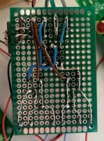
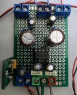
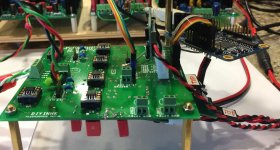
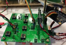
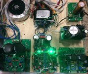
As promised, some pics of the test dac and test power supply board currently under development. The dac is working right now in with the dac chip operating in synchronous mode, clocked by the JLsounds I2CoverUSB board.
The dac board is an diyinhk ES9028PRO board that comes with the dac chip and one regulator chip installed on the otherwise bare board. The board is designed to work with through hole or SMD components. Opamps are all OPA1611.
Have tested the dac with 16/44 CD rips and using HQplayer (version 3 demo) to upsample to DSD. With a fast computer the best HQplayer algorithms sound very good (if the dac itself is good).
As is well known among people that have tried it, Sabre dacs typically sound better operating in synchronous mode and with upsampled DSD. Main problem with using HQplayer rather than AK4137 for that is cost. HQplayer costs much more than AK4137 and so does a fast computer. However, sound quality is better than AK4137 when HQplayer is running its best algorithms, IMHO. That being said, AK4137 can still sound excellent if properly implemented.
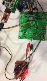
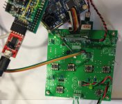
Dac registers are programmed by the existing Arduino setup borrowed from modded dac#2. Pretty soon the new dac will get its own Arduino.
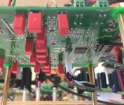
There are still things to work on, AVCC sound quality being one. The TP Trident regulators shown in the pics for VCCA, DVCC, and AVCC are all being fed 6.7v from an external regulator on the power supply board. AVCC Trident does not have added load resistors at the moment, but trying that did help sound quality with another dac.
The dac board is an diyinhk ES9028PRO board that comes with the dac chip and one regulator chip installed on the otherwise bare board. The board is designed to work with through hole or SMD components. Opamps are all OPA1611.
Have tested the dac with 16/44 CD rips and using HQplayer (version 3 demo) to upsample to DSD. With a fast computer the best HQplayer algorithms sound very good (if the dac itself is good).
As is well known among people that have tried it, Sabre dacs typically sound better operating in synchronous mode and with upsampled DSD. Main problem with using HQplayer rather than AK4137 for that is cost. HQplayer costs much more than AK4137 and so does a fast computer. However, sound quality is better than AK4137 when HQplayer is running its best algorithms, IMHO. That being said, AK4137 can still sound excellent if properly implemented.
Dac registers are programmed by the existing Arduino setup borrowed from modded dac#2. Pretty soon the new dac will get its own Arduino.
There are still things to work on, AVCC sound quality being one. The TP Trident regulators shown in the pics for VCCA, DVCC, and AVCC are all being fed 6.7v from an external regulator on the power supply board. AVCC Trident does not have added load resistors at the moment, but trying that did help sound quality with another dac.
Attachments
AVCC Trident does not have added load resistors at the moment, but trying that did help sound quality with another dac.
Just tried adding a 39-ohm, 1/2-watt resistor from each AVCC regulator output to ground. Same result as with the previous dac: It sounds much better. Still suspect there is probably a little more SQ improvement that can be obtained with a bit more work on AVCC, but its getting pretty good at this point.
Just tried adding a 39-ohm, 1/2-watt resistor from each AVCC regulator output to ground...
After performing harmonic distortion compensation, found that I could hear a little bit more improvement in sound quality by increasing Trident regulator input voltage to 7.0v (Warning: not all ADM71xx regulators that may come installed on some Trident boards are rated for more than 5v input. Please read part numbers and check data sheets carefully to make sure whatever you may be contemplating will be safe).
While things are going on in the background, perhaps this would be a good interlude to talk about how to play DSD512 from HQplayer, or whatever Roon can do without HQplayer, for the Chinese ES9038Q2M board we mod in this thread. The hardware part involving the clock and I2S is probably the easier part for most people. Little to it actually, the biggest thing being removal of the 100MHz clock on the dac board and replacing it with a u.fl connector. No harder than a clock swap, probably easier.
The bigger issue for most people would be programming the dac registers for synchronous operation. Only a few registers have to be set, but regardless of the exact number, some kind of Arduino (or perhaps another MCU) would be necessary.
One alternative to using a Sparkfun level translator might be to use a galvanic isolation chip, such as Si860x. We could talk about how to do that as well.
It could be that the low cost solution for using AK4137 would also involve synchronous dac chip operation. I did it using asynchronous dac operation, yet with AK4137 output operating synchronously with the dac chip clock. It could turn out the totally synchronous way is easier and lower cost to implement. We just have to try it to see.
Any takers on any of the above, or would it be better to wait until I have done more of it myself first?
Last edited:
")
I'm a Roon user and use the Roon upsampling capabilities. I haven't got as far as adding a Amareno USB to IIS yet so I'm stuck at the limitations of the SPDIF output from my Allo DigiOne'd RPi.
I upsample to the max of 192kbps using Roon and then use the AK4137 to further upsample to DSD 256 on the 9038.
This whole 9038 journey has been fun, I'm still learning a lot. I'm definitely going to have a good look at the 4499.
I'm hoping to make a start on the I/V and I have a question on the selection of resistors/capacitors on the -ve feedback loop. I can see on Jens' design he's using 470pf and 1.27k, on ESS application note 100pf/272 and on Mr Slim's 330pf/820. How are these determined?
Last edited:
- Home
- Source & Line
- Digital Line Level
- ES9038Q2M Board