Thanks for going that effort: a picture makes things easier at first glance, much appreciated ")
The PS bits look quite Ok to my novice eyes, but, err, doesn't your transformer need more than 15V outputs in order to have real 15V after the regulators ;-)
I understand you wanted to mix aswell some signal paths into that schematic. Why not... can't judge on this, but then wouldn't you need signal connection between the AK4137 and the ESS DAC ;-)
Thanks again, makes things clear and hence easy to spot possible misses...
Claude
Hi Claude,
Thanks for your comments.
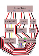
You're right my mistake, again. The i2s connections between the ak4137 and dac should be on the other side. Modified diagram is attached below, thanks for pointing that out.
Regarding the PS, transformer is r-core 50va(aliexpress). Two 15v secondary can power the lm317/337 even up to 16-17v(measured by multimeter) as it is adjustable, don't ask me how as I have no idea. Plus, the transformer stays cool, not even warm when run. So does the voltage regulators.
Regards,
Kay
Thanks for your comments.
You're right my mistake, again. The i2s connections between the ak4137 and dac should be on the other side. Modified diagram is attached below, thanks for pointing that out.
Regarding the PS, transformer is r-core 50va(aliexpress). Two 15v secondary can power the lm317/337 even up to 16-17v(measured by multimeter) as it is adjustable, don't ask me how as I have no idea. Plus, the transformer stays cool, not even warm when run. So does the voltage regulators.
Regards,
Kay
Attachments
Like this is ok?
Yes, something like that should be good to try. See what you think.
Guys,
The story on transformers is that they are rated for RMS volts at full rated current. First, the peak voltage is 1.414 times the RMS voltage (for a sine wave). The peak voltage is reduced by the voltage drop across the bridge rectifier which is about a 1.4v loss if using regular silicon diodes. Second, the voltage from the transformer will be reduced by its internal resistance depending on how much current is drawn, with the drop being equal to I times R. Given the above factors, if the transformer is running at low current and if there is a big filter cap after the bridge rectifier then the cap might be able to charge up to the peak voltage (that remains after subtracting the rectifier drop) and not droop in voltage very much before the next charging pulse. If the the circuit only discharges the cap slowly, then the input voltage before the regulator may remain higher than you might expect.
My audio designer friend says he usually runs maybe a bit less than 10v across non-LDO regulators, as he thinks conventional regulators tend to sound best for analog audio circuits in that case. He also uses transformers rated for more current than he expects to draw so that the transformer source impedance is lower than otherwise, and its core operates at lower flux densities. That's for torroidal transformers, which it happens are often wound so as to be not too far from saturation (which is not a good thing). E-core transformers tend to be better in that respect because the standard rectangular winding window area vs core size makes it hard to over-wind the coils.
Last edited:
Guys,
My audio designer friend says he usually runs maybe a bit less than 10v across non-LDO regulators, as he thinks conventional regulators tend to sound best for analog audio circuits in that case. He also uses transformers rated for more current than he expects to draw so that the transformer source impedance is lower than otherwise, and its core operates at lower flux densities. That's for torroidal transformers, which it happens are often wound so as to be not too far from saturation (which is not a good thing). E-core transformers tend to be better in that respect because the standard rectangular winding window area vs core size makes it hard to over-wind the coils.
That's not quite how transformers work - but don't worry, most people don't understand transformers very well, even EE's.
Running the transformer with a lower secondary current will not significantly affect the core flux density. The primary voltage, it's frequency, the number of turns, the core material and cross section will. If you want your transformer to run at a lower flux density, further away from saturation, you have to have it custom wound to do such. It will be running at that flux density with no load.
WRT E-core transformers being better for not saturating due to smaller winding window and being harder to 'over wind' - this doesn't make sense.
To run the core at lower flux, you need to have MORE primary windings, not less.
The trade off running core at lower flux is everything else suffers such as regulation (OP impedance) and size gets larger for a given VA.
This is just touching on the subject. All transformer designs have advantages and disadvantages.
T
.
To run the core at lower flux, you need to have MORE primary windings, not less.
Let's see if IIRC...
Flux depends on amp-turns (magnetizing induction) vs magnetic path length. With a bigger winding window area more amp-turns can be wound, and for a circular flux path (torroid) the ratio of window area to path length is maximized. On the other hand, the rectangular winding windows of E-cores and their longer magnetic path give a ratio that that is less easy to drive into saturation. One can only get so much copper into the window, even if using square cross-section wire. Amp-turns is then limited by resistive heating of copper.
Flux density, too much of which is what can cause saturation, depends on total flux vs the cross-sectional area of the core normal to the direction of the magnetic field lines. Frequency matters too, really volt-seconds integrated over one-half cycle. Increasing core cross-section reduces flux density, and makes the winding window smaller (for a particular effective magnetic path length). However, E-core and torroids come in standard form factors, so changing cross section or window shape is not usually an option. Basically, one must choose from standard core sizes.
In the case of a transformer with an open secondary, leakage and mutual inductances limit primary winding current.. There will be more inductance with more primary turns. Secondary current creates a counter flux so the total flux stays close to the same.
My friend has his torroids custom wound so as to keep them low resistance, far from saturation, and with extra electric and magnetic field shielding.
Also, its been awhile since I thought much about this subject. Slowly, some of it is coming back. Need to look up my old notes.
Last edited:
i agree that secondary current will not significantly affect the core flux density. a power transformer running near to saturation will be very hot, so we don't have to worry about that if a device operating at a normal temperature.
one most obvious downside of the toroidal transformer is it's wider bandwidth. the perfect function of a power transformer is passing by only 50/60 Hz, any other frequencies will potentially bring sonic disadvantages.
one most obvious downside of the toroidal transformer is it's wider bandwidth. the perfect function of a power transformer is passing by only 50/60 Hz, any other frequencies will potentially bring sonic disadvantages.
i agree that secondary current will not significantly affect the core flux density. a power transformer running near to saturation will be very hot, so we don't have to worry about that if a device operating at a normal temperature.
one most obvious downside of the toroidal transformer is it's wider bandwidth. the perfect function of a power transformer is passing by only 50/60 Hz, any other frequencies will potentially bring sonic disadvantages.
Exactly on both counts.
When a transformer is running hot with no or low load you can almost be assured that
it's core is running too 'hard' (high a flux density). Often this is purely because the core material is cheap rubbish and not capable of running at a high fux density.
You can easily measure it too with a simple variac and current meter. As you ramp the primary volts up, with no load, there will be a point where the current starts rising rapidly.
Yes, the Toroid has very good coupling between the primary and secondary. as such makes a great wide band transformer.
T
My friend has his torroids custom wound so as to keep them low resistance, far from saturation, and with extra electric and magnetic field shielding.
Custom winding isn't going to help with both low resistance (i.e. low copper losses) and keeping far from saturation. They're mutually opposed - the further you run from saturation for a given core material, the more copper losses you have to accept. Silver wire would help to lower resistance I guess.
Custom winding isn't going to help with both low resistance (i.e. low copper losses) and keeping far from saturation. They're mutually opposed - the further you run from saturation for a given core material, the more copper losses you have to accept.
It also depends on geometry, core size and shape. A larger core for a power transformer would probably be more cost effective than silver wire.
Last edited:
Custom winding isn't going to help with both low resistance (i.e. low copper losses) and keeping far from saturation. They're mutually opposed - the further you run from saturation for a given core material, the more copper losses you have to accept. Silver wire would help to lower resistance I guess.
Yes - well, sort of
If your design intent is to have the core running at a lower flux density then it will have to be a custom wound transformer. All 'normal' Toroids will run the core at a pretty high flux, around 16 and up to 18 kGauss (1.6 / 1.8 T)
to get the efficiency up.
Having said the above, I'm not absolutely convinced that running lower flux will result in better sound. There are so many different factors that we are juggling here.
My best guess is there is possibly a sweet spot that is retaining most of the benefits of high core flux but just backed off from saturation a little more
to keep it well in linear region.
But I have not done definitive testing of this with all other factors being equal.
T
My best guess is there is possibly a sweet spot that is retaining most of the benefits of high core flux but just backed off from saturation a little more
to keep it well in linear region.
Sounds reasonable.
Hey. I already got the protection fee. Arduino's on the way somewhere. Ready according to your recommendations to change the settings es9038q2m. I removed the AVCC film caps like you said. And then removed the ceramic capacitors on the es9038q2m Board that filter the AVCC power line next to the chip. And the sound stopped being sharp. the problem went away. Through what service can I upload photos to the forum?May I ask if anyone has gotten started yet with Arduino or other means for accessing registers?
Through what service can I upload photos to the forum?
You can attach jpg files less than 1MB in size if you click on the advanced editing button and or scroll down to the 'manage attachments' button located below the reply/editing window. The images will be stored at diyaudio. I usually crop pictures, then reduce jpg quality until file size is under the 1MB limit (assuming the file was too big to attach without editing).
Regarding film caps, I'm not sure which ones you mean. Perhaps I don't remember what you were using for AVCC before?
Last edited:
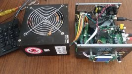
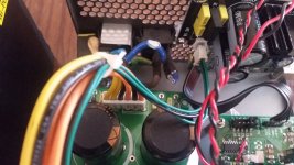
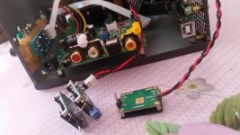
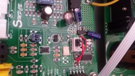
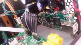
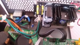
I use TPS7A4700 for AVCC. And to remove the sharpness in the sound, I added the output ldo film 47 nF. After your criticism, I removed them. now there are, if I'm not mistaken, 57 nF ordinary ceramics. Here is a photo. This is a temporary structure. To looked good and was easy to change something at any moment.You can attach jpg files less than 1MB in size if you click on the advanced editing button and or scroll down to the 'manage attachments' button located below the reply/editing window. The images will be stored at diyaudio. I usually crop pictures, then reduce jpg quality until file size is under the 1MB limit (assuming the file was too big to attach without editing).
Regarding film caps, I'm not sure which ones you mean. Perhaps I don't remember what you were using for AVCC before?
Attachments
I use TPS7A4700 for AVCC.
I started looking into using LDOs for AVCC, at least a little bit. So far only tried ADM7150 (a recent issue Twisted Pear Trident-SR). Didn't sound very good at first. Tried adding a 33-ohm, 1/2-watt resistor from the regulator output to ground. That seemed to improve sound quality some. I then increased the input voltage to the ADM7150 from 5v to 5.7v, and then to 6.7v (using an adjustable pre-regulator in this case). Sound quality seemed best using 6.7v for the input. I did not notice further improvement going to slightly higher input voltages, so I stopped at 6.7v to minimize unnecessary heating of the regulator.
I recently have been advised that it is not unusual for adding a resistor from the voltage regulator output to ground to improve sound quality in analog audio circuits. I kind of assume it works by reducing the source impedance seen by the load over a fairly wide range of frequencies. Similarly, I was advised that increasing regulator input voltage may also help improve sound quality.
Pretty soon I hope to be able to compare a few different +-15v regulators. More on that later.
I recently have been advised that it is not unusual for adding a resistor from the voltage regulator output to ground to improve sound quality in analog audio circuits. I kind of assume it works by reducing the source impedance seen by the load over a fairly wide range of frequencies. Similarly, I was advised that increasing regulator input voltage may also help improve sound quality.
Its certainly the case on the older, non-LDO regulators that the output impedance decreases with increasing load current. That's because the output device is an EF whose transconductance is directly proportional to its Ie. On LDOs with common-emitter output devices the effect is likely similar. With a MOSFET as pass device though the gm isn't a linear increase with output current but I'd still expect lower Zout at higher load currents.
Its certainly the case on the older, non-LDO regulators that the output impedance decreases with increasing load current. That's because the output device is an EF whose transconductance is directly proportional to its Ie. On LDOs with common-emitter output devices the effect is likely similar. With a MOSFET as pass device though the gm isn't a linear increase with output current but I'd still expect lower Zout at higher load currents.
Most newer LDO's do not have EF outputs which enables the very low dropout voltages that they achieve.
However, the OP device will still have a higher gm when running at higher currents, so we can still be talking about the same mechanism, being that the error amp is doing less work, so to speak.
But my intuition tells me this is an oversimplification of a more complex situation and we don't know the driver arrangement or the exact compensation network. The first thing I would be looking at is the regulator's transient response at various output currents and capacitor arrangements.
T
- Home
- Source & Line
- Digital Line Level
- ES9038Q2M Board