Don't know about total nonsense for something that works. However, I only tried what I described, as I keep trying to make clear. The 10,000uf electrolytics I tried were rated for .053 ohms ESR. My LCR meter also showed they were very low at 10kHz, but couldn't get a reading at 100kHz. Could be dielectric absorption is where the problem lies, and I don't know how audio grade caps can prevent that. Still, I would be happy to try some of the caps you suggest next time I place an order.
Also, the opa's sound excellent with the film caps. No reason to change what works there. If I could just get the clock jitter down where I want it, the dac would be a step closer to DAC-3 (which uses LME49860 opa's and is rated A+ recommended by Stereophile).
Also, the opa's sound excellent with the film caps. No reason to change what works there. If I could just get the clock jitter down where I want it, the dac would be a step closer to DAC-3 (which uses LME49860 opa's and is rated A+ recommended by Stereophile).
Last edited:
Don't know about total nonsense for something that works. However, I only tried what I described, as I keep trying to make clear. The 10,000uf electrolytics I tried were rated for .053 ohms ESR. My LCR meter also showed they were very low at 10kHz, but couldn't get a reading at 100kHz. Could be dielectric absorption is where the problem lies, and I don't know how audio grade caps can prevent that. Still, I would be happy to try some of the caps you suggest next time I place an order.
Also, the opa's sound excellent with the film caps. No reason to change what works there. If I could just get the clock jitter down where I want it, the dac would be a step closer to DAC-3 (which uses LME49860 opa's and is rated A+ recommended by Stereophile).
Mark could you kindly test filtering the +-15V rails using 680-1000 uF Panasonic FC + (1-10) uf + 100 nf Wima mks. This set should be filtering all frequencies spectrum.
Film caps are not included in the output stage caps. Since I am trying to design a PCB would thet be wise to add film caps as close to OPA's leads as possible?Also, the opa's sound excellent with the film caps.
Last edited:
idir,
I have no doubt that all frequencies are being filtered. I have tested film caps with more than one power supply with different filter cap designs and with more that one type of dac.
Also, I tested the film caps very close, within inches of the output stage using large gauge wires. It isn't RF at a high enough frequency that the distance makes any significant difference. I have been doing this stuff for decades and prior to retirement was well regarded as a professional EE. However, I try to explain things in simple terms here for beginners. Don't let that make you think I don't know more than I talk about here. Also, some of the things I am working on now nobody really knows how to do best. If it was generally well known in the profession I wouldn't have to be doing it, I could just cookbook it.
In addition, I have discussed the film caps in another thread, in the context of Katana dac. You may find this post of interest:
https://www.diyaudio.com/forums/pc-based/329911-getting-allo-coms-katana-dac-17.html#post5653092
Then there is Greg Stewart's comments to me about halfway down this post:
https://www.diyaudio.com/forums/pc-based/329911-getting-allo-coms-katana-dac-17.html#post5653697
What Greg say about the caps is the same as others have found. What he says about his best power supplies is no doubt true, he spends a fortune on them. But, even at lower cost there is more than one way to make a good power supply. Film caps are one way that can help when best sound quality is desired. There are other ways too such as the power supplies in DAC-3. Neither DAC-3 supplies nor my film caps are super cheap, but they both work (sorry about the cost, don't know a cheaper way). Greg's expensive supplies are likely over the top for our needs.
Lastly, I wouldn't make too much of the comments by janos. He has never modded a dac like this one as far as I have. What sounds best in terms of opamps changes as the dac design becomes cleaner and more refined. He happens to prefer swapping in his favorite discrete opamps even though I keep telling him over and over that some very best dacs in world use IC opamps like I do. That includes the example I gave of Benchmark DAC-3. If he wants to mod a dac along with us, and listen to what they actually sound like as modded, then I would take his suggestions more seriously. We have this same argument every month or two. I just get tired of giving the long explanation every time in response to him. Waste of my time.
Last edited:
idir,
To explain a little more in terms of the technical issues, it isn't a matter of whether or not frequencies are getting filtered. They are filtered and regulated pretty well even in the absence of film caps. Just not well enough. Why? Likely has some thing to do with Dielectric Absorption (DA), something good film caps have almost none of and electrolytics have a lot of. There have been arguments among engineers about what effect on sound quality it might have, especially if the amount of it is fairly small. Personally, I happen to be very picky about sound quality, and the sound of our modded dac and the sound of Allo Katana dac sound broken to me when compared to the sound of Benchmark DAC-3 unless I add film caps to the modded dac and Katana. Perceptually speaking, the caps smooth out and effectively eliminate some very-objectionable-to-me graininess to the sound quality. In this dac modding project, my goal is to get the best sound quality possible at lowest possible cost. When I can find lower cost ways to get the best sound quality, I will use lowest cost. But, sound quality comes first on this project, not cost. I can't say that I know of a lower cost film cap, or equally effective alternate solution at this time other than what I have put forth. Over time, maybe various subsections of the dac project can be revised for lower cost, don't know. I can only do so much at once, and right now my focus is in other areas.
If interested, there is lots of info on the web about the DA behavior of caps:
dielectric absorption ladder network model - Google Search
Last edited:
Just looked over the Kemet film cap data sheet some more. Noticed that dissipation factor is not rated for 10kHz. Also, in the maximum current vs frequency graphs, 100uf and 47uf caps are not rated for use over 10kHz. Those are worrisome signs. We should probably forget those, and stick with Wima instead.
EDIT: Looking at similar graphs for the Wima caps, looks like 22uf are the biggest ones fully rated up 100kHz. They don't show a graph for 33uf, but for 47uf, the graph ends at about 50kHz. That suggests the combination of Wima caps that I used might have benefits over using only 33uf values in parallel. Thus, probably best to use the exact values I did if that is an option for you.
Mark, most film caps go way past 100kHz, as long as the construction includes sprayed / conductive glued end caps. This parallels all the windings, I've measured Solen 250V PP cylindrical caps with very low Z up to MHz
region. Generally the leads have more inductance than the cap itself.
If you are using Polyester caps, it's worth trying Polypropylene, even if they
are physically larger.
Also, I recommend you give your clock PS the same treatment.
T
Mark, most film caps go way past 100kHz, as long as the construction includes sprayed / conductive glued end caps. This parallels all the windings, I've measured Solen 250V PP cylindrical caps with very low Z up to MHz
region. Generally the leads have more inductance than the cap itself.
Also, I recommend you give your clock PS the same treatment.
T
Agreed they may be effective to some extent up to a few MHz, especially the smaller lower value ones. However, not necessarily as effective as I need for output stage power sound quality.
I did a test with some 33uf Wima film caps only. Five of them parallel per +-15v rail (gives 165uf per rail). I don't think they sound quite as good as the bunch with only 108uf total per rail, which are made with a mix of smaller values too. They are 10+10+22+33+33 (all in uf). The smaller caps may help audibly at higher audio frequencies. When I get a chance I may do some more tests to see if my impressions hold, but I think they probably will. I have tried a couple of different times already.
Interesting point you raise about the clock. I should give it a try with some smaller value Wima's I have. They are .1 uf and 1uf.
Last edited:
Mark
Seems you are the man in charge ;-) so I will just go with your recomendations.
Could you please help me with the final BOM to the unbalanced output schematic.
Once you approve the schematic and PCB layout I would upload the pack in a zip file here.
For now the draft sch. View attachment output_stage_schematic.pdf
Agreed they may be effective to some extent up to a few MHz, especially the smaller lower value ones. However, not necessarily as effective as I need for output stage power sound quality.
I did a test with some 33uf Wima film caps only. Five of them parallel per +-15v rail (gives 165uf per rail). I don't think they sound quite as good as the bunch with only 108uf total per rail, which are made with a mix of smaller values too. They are 10+10+22+33+33 (all in uf). The smaller caps may help audibly at higher audio frequencies. When I get a chance I may do some more tests to see if my impressions hold, but I think they probably will. I have tried a couple of different times already.
Interesting point you raise about the clock. I should give it a try with some smaller value Wima's I have. They are .1 uf and 1uf.
Thank you Mark!
It was very instructive.
I'll order today 4x10 + 2x22 + 4x33 to copy your setup.
btw, I ordered Trident-SR 3.3V Series Regulator Module to replace my lt3045 for avcc and hear if it makes some positive difference.
Hi terry22,
You are welcome as always. If you want, you can always ask questions and I will try to explain things. I know the film cap thing is controversial to some, and that it costs more to do it well than any of us would probably prefer. It does work though, which was determined by testing, not just modeled or conjectured. Also, hope the Trident AVCC regulator works to your satisfaction, please tell us how you like it when you get a chance.
Regarding film caps and this project vs Katana (which I think you may also be pursuing), right now I like the modded dac project sound and general purpose nature better than Katana in some ways, but I like Katana sound quality better in terms of jitter-related artifacts. I have heard the modded dac produce very low jitter like Katana does, but not with it stable for long enough to use for a design. I am trying to see if I can find a way to get jitter better while keeping the 100Mhz dac clock and avoiding master mode and or fifo type solutions. For the modded dac to be able to play all sample rates, and to be truly general purpose we can't have the limitations those approaches bring. Don't know if I will succeed yet, but at least I'm not ready to give up. In any case, the modded dac sounds very good and is something I think people can be happy with. It could also be hooked up to RPi as occip has described, if that were of interest. Still, if I can keep making better, I will.
idir,
The schematic you attached looks basically correct. However, which pin numbers it makes the most sense to use in some ways depends on how the layout looks. That is to say, there are two opamps in each IC. For example, which of the two opamps is used for I/V of which dac output depends on which way makes for the most sensible layout. Can't comment on that yet, would have to see a PCB layout. I can say that I like the layout I did for the hand wired thorough hole component output stage in the sense that I thought it was reasonably rational, compact, and efficient. I can also say that I would rather see some hand wiring of traces even on a PCB if it is needed to help preserve the integrity of an effective ground plane.
The schematic you attached looks basically correct. However, which pin numbers it makes the most sense to use in some ways depends on how the layout looks. That is to say, there are two opamps in each IC. For example, which of the two opamps is used for I/V of which dac output depends on which way makes for the most sensible layout. Can't comment on that yet, would have to see a PCB layout. I can say that I like the layout I did for the hand wired thorough hole component output stage in the sense that I thought it was reasonably rational, compact, and efficient. I can also say that I would rather see some hand wiring of traces even on a PCB if it is needed to help preserve the integrity of an effective ground plane.
Last edited:
Today working on design layout for a DS90LV018A one-channel differential line receiver to single-ended LVCMOS output to drive the clock input on one of the AK4137 boards. The receiver will be mounted on a small Surfboard attached to the underside of the AK board, and it will get power from the 3.3v LDO on top that previously provided power to the 22.5MHz (or 25MHz recently tested) clock that has been removed. u.fl connectors will be attached to the receiver Surfboard for inputs and output. u.fl to SMA adapter cables will bring differential clock output signals from the clock divider board to the receiver. Clock input to divider board will come from a copy of the dac chip MCLK signal routed out through a GPIO pin. Lots of work to test an idea that may or may not work, but what else can one do? Too many things unspecified in AK and Q2M data sheets to know exactly what they need to work in a ultra-low jitter compatible configuration. Pictures will be posted later as construction progresses enough to show something.
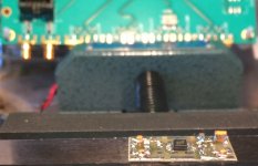
A little ongoing progress preparing for some testing in the near future. A pic is attached below showing the LVDS to LVCMOS adapter board. In the background, and unfortunately rather out of focus, is the clock divider chip evaluation board. The adapter board has .002uf, .1uf ceramics, and 10uf tantalum polymer decoupling caps in the back right corner. Need to see if I can get a .01uf ceramic in there somehow too. On the left are two u.fl connectors and some SMD 50 ohm SMD resistors for the LVDS differential inputs. Two 50 ohm resistors are in series to terminate the LVDS signals with 100 ohms. On the right is the single LVCMOS compatible output and its u.fl. connector.
Just have to keep doing a bit each day so this keeps moving along. Sure would be nice if it works, but we'll just have to see if I get lucky or not.
Just have to keep doing a bit each day so this keeps moving along. Sure would be nice if it works, but we'll just have to see if I get lucky or not.
Attachments
Looking at buying one of these and learning to modify it. Can someone answer a couple questions about it? What is the voltage output on the rca's and can it be modified? I see a white connector on the board, one diagram labels it iis. Is this used to interface with other boards? Can I design ways for this to interface with other input devices by attaching a board to it? If this is not the right thread to ask basic questions then I apologize. Thank you.
Oh yeah, is it a bad idea to buy one off ebay? Do some manufacturers use inferior components?
Oh yeah, is it a bad idea to buy one off ebay? Do some manufacturers use inferior components?
Last edited:
Hi Bret,
You are definitely in the right place to ask those kind of questions. The RCA output voltage is the same as the voltage on the 1/8" stereo jack, which is about 2V RMS, also known as line level. It should be about enough to drive most power amps.
The IIS input, aka I2S, is one of three inputs on the dac board. That input is most commonly used for USB input, either directly from a little USB to I2S converter board, or with an intervening AK4137 sample rate converter board.
The best dac boards for modding are this brand (with or without the optional display): ES9038 ES9038Q2M DAC Decoder board Support IIS DSD 384KHz Coaxial Optical DOP | eBay
ES9038 ES9038Q2M DAC Decoder board Support IIS DSD 384KHz Coaxial Optical DOP For hifi amplifier audio Rectifier power supply -in Amplifier from Consumer Electronics on Aliexpress.com | Alibaba Group
Most USB to I2S boards are either XMOS or Amanero (original or clone) types:
2018 XU208 XMOS USB U8 Audio Asynchronous Card DSD II2S PCM Amanero | eBay
AK4137 boards come in two varieties:
AK4137 I2S/DSD Sample Rate Conversion Board Supports PCM/DSD Interconversion DOP | eBay
HIFI AK4137 DAC SRC flagship high-end audio 786K 32Bit DSD256 DSD IIS conversion | eBay
...with the more expensive ones including SPDIF and TOSLINK inputs. The low cost version is I2S input only.
EDIT: Most people seem to buy the above items through ebay and aliexpress.com. It can pay to shop around to find the lowest price. There are some cheaper dac boards that can be modified too, but connecting an external microcontroller to access the dac chip control registers is much easier with the recommended brand. If considering a lower priced dac board, please post a link here before ordering so we can verify if it is likely to be a good choice. There are some that look sort of similar, but really aren't similar enough. The lowest cost boards that can be used are some blue color ones that otherwise look pretty close to the ones I linked to. https://www.aliexpress.com/item/ES9...46-4e53-94dc-52449da266c6&transAbTest=ae803_5
Last edited:
Hi Bret,
The RCA output voltage is the same as the voltage on the 1/8" stereo jack, which is about 2V RMS, also known as line level. It should be about enough to drive most power amps.
The IIS input, aka I2S, is one of three inputs on the dac board. That input is most commonly used for USB input, either directly from a little USB to I2S converter board, or with an intervening AK4137 sample rate converter board.
Thanks for the reply.
USB was where I was going with this. Perfect.
Can you estimate how much cost the coaxial and optical inputs add to overall cost of this product? I won't use them. If the cost of these is negligible, I will just live with having them on there.
What controls the line level voltage? Can I change it, or is it controlled by the processor?
Can you estimate how much cost the coaxial and optical inputs add to overall cost of this product? I won't use them. If the cost of these is negligible, I will just live with having them on there.
What controls the line level voltage? Can I change it, or is it controlled by the processor?
The coaxial and optical inputs on the dac board come with all the boards that we might use for this project. The components could be removed from the board, if desired. Since there are no otherwise suitable boards to use as a starting point for this project, an incremental cost for the extra inputs is not available. (Hypothetically, it might be that the extra inputs could come in handy sometime for troubleshooting purposes. If, for example, no sound out of the dac board, one of the extra inputs could be used to inject a test signal. If the dac starts working in that case, it can help to narrow down where to go looking for the problem.)
Volume is controlled digitally inside the dac chip. There in an MCU (microcontroller) on the dac board with pins for connecting a potentiometer. The MCU reads a DC voltage on the pot and uses that information to program the dac chip registers. Alternatively, since we recommend to eventually control the dac chip from a different MCU anyway (Arduino or Raspberry Pi), that new MCU could also be used to program the dac chip output volume level.
Last edited:
Great. This looks like a good starting project that I can learn from. I take your word that 2v is a sufficient line level, I still want to experiment with it.
2v RMS should probably be about right. There is about 3v peak to peak after the first I/V amplifier stages, good, yet still low enough to prevent some types of distortion from creeping in. I probably would not recommend messing with gain much in the existing output stage since those amplifiers are also negative feedback filters (mainly the differential summing amp), and changing one thing affects other things. But if you need more level, an add-on output buffer opamp for each channel would be fine.
Another option that can save some construction work and pick up a little extra free output level might be to use a Twisted Pear Trident AVCC voltage regulator. They make them slightly hot at 3.6v rather than the standard 3.3v for whatever reason, probably just for that little free output boost. I don't know how Trident sounds compared to the opamp circuit we normally use for AVCC, but I'm guessing both approaches are likely to sound about the same. One of these days I will have to try it myself to see.
Last edited:
I should probably also mention there a post back some pages with an attachment file containing links to lots of possible posts of interest in this very long thread: https://www.diyaudio.com/forums/digital-line-level/314935-es9038q2m-board-320.html#post5609058
I should probably also mention there a post back some pages with an attachment file containing links to lots of possible posts of interest in this very long thread: https://www.diyaudio.com/forums/digital-line-level/314935-es9038q2m-board-320.html#post5609058
Yes, I meant to ask if that existed. 300+ pages is a lot to sort through.
I have another question. I read that the processor consumes 500mW. The complete working board requires 15v and some use dual 15v inputs. Is there a particular function that requires so much power, or is it more or less the sum of all the components working together that adds up to such high power consumption?
Last edited:
- Home
- Source & Line
- Digital Line Level
- ES9038Q2M Board