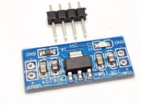
3.3v regulator modules are something like this:
10pcs AMS1117 3.3 DC DC Step Down Power Supply Module 4.5V 7V To 3.3V Voltage Buck Board Regulator Adapter Convertor-in Integrated Circuits from Electronic Components & Supplies on Aliexpress.com | Alibaba Group
they are a good price, so i just get more to grade them in pairs for avcc.
10pcs AMS1117 3.3 DC DC Step Down Power Supply Module 4.5V 7V To 3.3V Voltage Buck Board Regulator Adapter Convertor-in Integrated Circuits from Electronic Components & Supplies on Aliexpress.com | Alibaba Group
they are a good price, so i just get more to grade them in pairs for avcc.
Attachments
Last edited:
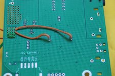
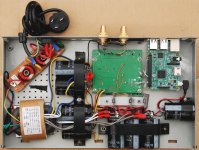
having big cap is advantage, i use eight 10,000uf rubycon capacitors, 4 for +-15v, 2 for rpi +5v and dac +5v, 2 for dac avcc and vcca.
two 7815, a 7815 and a 7915 are underneath the three 1117's. 2 orange wires are chl and chr avcc, 2 green wires are vcca.
i made several units of this for myself and my friends, we all very happy for the sound quality.
it's quite straightforward, enjoy it.
cheers
two 7815, a 7815 and a 7915 are underneath the three 1117's. 2 orange wires are chl and chr avcc, 2 green wires are vcca.
i made several units of this for myself and my friends, we all very happy for the sound quality.
it's quite straightforward, enjoy it.
cheers
Attachments
Hi eslei,
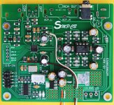
Very interesting approach you take there. You sure do a nice job of unsoldering and cleaning up the PCB. Very nice work.
I wonder if you might be willing to say a little about how you arrived at your particular modding choices? Did you do much trial and error, or just come up with a plan and go for it, or maybe something quite different?
It is interesting to me that you decided to keep the one opamp output stage using voltage mode, even though we know distortion is quite a bit higher that way. Guess you must like it okay, otherwise you probably would have changed it. Wonder if you ever tried Victor's approach to an output stage?
Hello PJN. Could you elaborate a little? I have a board ordered and plan to start with some simple stuff but it would be great to see what you have planned.
Alex,
One thing you might think about a lot before customizing a case with holes is that you might want to add something like an AK4137 board at some point, but maybe you don't know if you will or which size you might prefer. Also, if going for the more expensive AK4137 it has SPDIF and TOSLINK inputs, which you might want to use instead of or in addition to such inputs on the dac board.
Then there are things you might decide to do like add output stage and or AVCC boards that can take up some space. You might go through some iterations with power supplies before you are done, too.
Various things like that were going through my mind when I looked at what PJN has done so far, and naturally, I'm not sure if it will close the door to some possible mods that might have been good from a sound quality perspective. I hope it doesn't. Of course, there are some people who have ways of making very nice cover panels with new hole patterns and things like that, which can look great. So, while I wait to see what builders will decide they want to do, I would advise those still thinking about how to start out from the very beginning to take it slow and see how sound quality satisfaction is coming along before committing to a mechanical layout beyond what might be needed for testing.
Last edited:
Hi Alex,
My strategy for this cheap board was to first see if it was worth doing mods to so I first picked up some decent/ not great power supplies on line. I already had an unused wavio USB to I2S so the basic configuration was set. I built a box from left overs in my garage I did read the super long mods thread here and took screenshots of the mods that I thought I could handle that could improve sound. So far I'm pretty impressed just with the PSU and op amp improvements. My next steps might be PSU improvements to the board and removal of coupling caps, maybe clock farther along.
My strategy for this cheap board was to first see if it was worth doing mods to so I first picked up some decent/ not great power supplies on line. I already had an unused wavio USB to I2S so the basic configuration was set. I built a box from left overs in my garage I did read the super long mods thread here and took screenshots of the mods that I thought I could handle that could improve sound. So far I'm pretty impressed just with the PSU and op amp improvements. My next steps might be PSU improvements to the board and removal of coupling caps, maybe clock farther along.
Hi guys, thanks very much for your replies and thanks PJN for sharing your strategy. Mark, I agree. I certainly won't commit to any sort of case until I finish. I'm thinking more about mods to the board and starting with some simple stuff first. I'm still piecing through everything and have no other choice than to take it slowly! I do want to use S/PDIF input so will definitely go down that route eventually.
There is an old saying, "If all else fails read the manual." Right now the 80-page AK4137 data sheet is in the process of being printed out. After studying it on the computer monitor for a while I am starting to get the idea that it might be worth hacking into the AK4137 board I2C bus to take over control of the AK4137 chip. What I am thinking is that it looks like AK4137 should be able to output DSD in slave mode with the ES9038Q2M as I2S bus (native DSD bus) master. In that case we should be able to use the NCO divider or whatever else there might be in Q2M to sync up the AK4137 in something a lot closer to master mode operation, or at least maybe with DPLL bandwidth set very low and, and with very stable operation at the same time. Not sure exactly how to do it yet, but its starting to look like it should be doable. If so, then it would hopefully solve the problem of reliably keeping jitter very low similar to Katana or DAC-3, while retaining all the benefits of a general purpose dac. We'll see how it looks after some more study of the data sheets. I'm feeling optimistic about it so far, though. More to follow after some study and mulling things over.
You're a legend !
I'm here in the workshop listening to Albatross....(yes...when Peter was The Man...) Raspberry Pi...MoOde audio...DIYinHK XMOS...AK4137...Es9028 in I/V mode, on the 'B' system and all is right with the world....
Next, inside and on the 'A' system....Plinius...Shahinians..... Bliss for Christmas ...")
Thanks Mark for your unstinting efforts and communicating to us all your discovery's..!!
I'm here in the workshop listening to Albatross....(yes...when Peter was The Man...) Raspberry Pi...MoOde audio...DIYinHK XMOS...AK4137...Es9028 in I/V mode, on the 'B' system and all is right with the world....
Next, inside and on the 'A' system....Plinius...Shahinians..... Bliss for Christmas ...
Thanks Mark for your unstinting efforts and communicating to us all your discovery's..!!
Last edited:
Hi KoAP,
Filters are always on in both the dac chip and in the AK4137 chip (although external filtering is possible for Sabre dac chips). It is that way since they both chips do some resampling. They are designed to use appropriate filtering depending on whether they are outputting PCM or DSD. That can get into a longer and more far ranging discussion, but in brief the default DSD filtering sounds better to me and is likely a good part of why DSD may sound subjectively better as we are using it.
Probably the main reason for adding something like Spartan 6 to a Sabre dac design would be to help make PCM filtering sound as good or better than the default DSD fitering. However, part of making PCM filtering sound good may also involve different clocking schemes for the different chips doing resampling. Finding good clocks for that which are purchasable in small quantities might be another issue to work through.
no hardware implementation at the moment can match HQplayer`s "xtr" filters. although running them will require a significant computing power. still upsampling to DSD256 and rather reduced version poly-sinc-xtr-2s on an old i7-2600 is the best source for ESS DACs I have heard so far.
more on this topic: Xtr Filters - Why do they sound so good? - HQ Player - Roon Labs Community
more on this topic: Xtr Filters - Why do they sound so good? - HQ Player - Roon Labs Community
eziitis,
Thank you for the info. Software upsampling likely would potentially sound best with a master mode dac. Then jitter reduction or low jitter design, and conversion to DSD can be separated from each other. On the other hand, if we want to upsample as a jitter reduction strategy and convert to DSD because we like the sound of the filters better, it might be better to try to figure out a good way to do them more or less at the same time in hardware. Other combinations might work too, such as conversion to DSD 128 in software, then upsampling that DSD to DSD 256 in hardware. Hard to say for sure without trying every possible combination.
What it all really all suggests is that our dacs are still not as good as the ADCs used for mastering CDs. If there is really good sound that was somehow encoded into 16/44 format, and then we have to go to extreme lengths to make it sound good when converting back to analog, that would seem to put the blame on the dacs for not being good at simply playing 16/44 very accurately or as accurately as some people would like.
On the other hand, maybe all the playback processing we are doing is making CD recordings sound better than what is actually encoded on the CDs.
My guess would be that as long as we keep getting things like more details out of cymbals that sound more and more like real cymbals, probably that information is there on the CDs alright, and probably we just need to keep working on making better dacs more affordable.
Also, since there is more than one way to make a dac, and I kind of have my mind set on learning about one possible way to make a pretty good general purpose dac, I think I will keep on plugging along as I am and not worry too much about other technological developments that keep coming along.
That being said, the new AK dac chip coming out pretty soon does look kind of interesting.
Traced out schematic for most of low-cost AK4137 board (excepting only display outputs). An MCU would need 10 I/O pins @3.3v (plus any additional I/O pins as desired for buttons and or display). An Arduino Trinket Pro 3.3v should be adequate for test purposes, and just happen to have one. Could be the same one controlling the dac chip, since the dac and the AK4137 should have two different I2C addresses.
Next step will be to take a detailed look at configuration options for AK4137 and ES9038Q2M which might be workable with Q2M acting as I2S/DSD clock master.
Next step will be to take a detailed look at configuration options for AK4137 and ES9038Q2M which might be workable with Q2M acting as I2S/DSD clock master.
..... maybe all the playback processing we are doing is making CD recordings sound better than what is actually encoded on the CDs.
no reproduction device will generate an absolutely identical sound to let say cymbals. since we know how the real cymbals sound, then all effort of playback processing here is to fool our brain regardless of what is actually encoded on the CD, imho.
- Home
- Source & Line
- Digital Line Level
- ES9038Q2M Board