Probably doesn't sound as interesting as it may look. It runs on a 5v wall wart and uses SMPS to develop dual rails, already a bad sign. Without seeing one close-up in person, hard to say too much more. But, every time I try one of the new low-cost Chinese ES9038Q2M variants, they always sound bad and are hard to make right. The one we mod here is sill the best layout I have seen for modding, if that were to be of interest.
") You always saving me in making a bad decision, i guess #1 is the best option. Thanks Mark
You always saving me in making a bad decision, i guess #1 is the best option. Thanks Mark... i guess #1 is the best option...
Actually, if thinking of modding then I would suggest like this: ES9038 Q2M DAC DSD decoding board supports IIS DSD 384KHz coaxial fiber DOP-in Integrated Circuits from Electronic Components & Supplies on Aliexpress.com | Alibaba Group
That is a good price for one with display, and with the display pin lifting can be avoided.
Last edited:
I am a bit hesitant to do all these pin liftings, I've had some weird past experiments which all ended with bricking.
Well, I also described and posted pics of a way to do it by trace cutting and patching instead of pin lifting. Besides, with an Arduino (or potentially an RPi) chances of bricking should be quite small. Only destruction of the dac chip could do that. Losing the MCU can be worked around by using Arduino to control the dac chip.
If unsure, one can always practice on scrap boards that one finds around, and or with SMD soldering practice kits. Some of it is skill, and some of it is just confidence to try even though it may look a bit intimidating.
Rules violating post removed that contained link to ESS confidential/proprietary information.
--- repeating some of the things from the removed post ---
@Mark4 - thanks for the explanation and all the links, things are starting to fall into place now.
I'll probably wont be able to do much until next month, but will keep an eye on how the driver discussion evolve.
I am a bit hesitant to do all these pin liftings, I've had some weird past experiments which all ended with bricking.
@eslei - thanks for posting your drivers, would it only work with i2c connectivity?
@Johnny HIFI - Maybe check out the one @eslei posted which seems to have an easier way to connect to i2c.. will make it easier to experiment with the upcoming tweaks
Well, I also described and posted pics of a way to do it by trace cutting and patching instead of pin lifting. Besides, with an Arduino (or potentially an RPi) chances of bricking should be quite small. Only destruction of the dac chip could do that. Losing the MCU can be worked around by using Arduino to control the dac chip.
If unsure, one can always practice on scrap boards that one finds around, and or with SMD soldering practice kits. Some of it is skill, and some of it is just confidence to try even though it may look a bit intimidating.
Markw4 thanks , I get what you mean but also the MCU bricking can be hard for me to start patching up later and I will probably have to look for another board
To me the board you showed in post #3357 looks not bad - seems some NDK clock (at least same form factor), integrated i/v stage (type of opamps not sure, but no extra wiring, no RF issues due to a separate added board and wires and muuuch less modding work) and probably a multilayer board with better GND shield (not sure).
the dual opamp SMPS could be removed and externally fed by a linear PSU and the AVCC which seems to have a LDO for each channel could be substituted by external opamp source. You get this with a display, housing, BT Integration and RC for 140 EUR on the bay - for me worth a trial if I would not have already 2 modded boards and I was afraid of going the i/v stage - clock modding path (SMD or TH).
Last edited:
here is the drivers, i test them on volumio v2.513. rpi pin 3 to sda, rpi pin 5 to scl.
detailed instructions later, i need some time to type.
Thank you for the driver.
Can't wait to get the installation details to test it.
terry22,
Am I mistaken, or do you already know something about I2S audio on RPi?
If not, there are some hardware connections you have to make, and then install the driver eslei posted. Do you need instructions for both hardware and driver installation?
Hi Mark, I knew a little connecting cards, using Gnd/Data/bclk/lrck.
I know a little SPI and I2C on Rpi.
The Hardware connections will be To connect RPI GPIO to SDA and SCL on the 9038q2m?
If it is right, then I only need instructions on adding the Driver in Raspbian.
terry22,
Hopefully, eslei will have a bit more to say pretty soon about getting the driver working. If I were to guess, and I know little about RPi, the driver may need to be copied to some directory and a system file edited to tell it to load the driver. Seems to me I had to do something like that for the first review testing of Allo Katana to install the driver. Does that sound familiar to you (or anyone else around here), or am I way off base?
I would also like to hear from eslei about whatever else he may have observed about DPLL stability in however he has his boards physically arranged, wired together, and powered. In other words, anything and everything that might be relevant. More about my own continuing efforts a little later.
Getting back to DPLL stability, I tried another bit of testing today. Reinstalled my 1st modded dac into the test system. Also, yesterday I tried putting a couple of layers of copper foil under the test setup board in the server case. One layer of copper foil was attached to the bottom of the test perfboard that everything else is mounted on. Another layer of copper was attached to the bottom inside of the steel case. There is a air gap separating the two copper foil layers. The copper foil on the bottom of the perfboard is insulated from the steel case and I brought up a ground wire with alligator clip to see if grounding one layer of copper had any effect.
With both the new modded dac and the 1st modded dac, the layers of copper foil don't help at all, not does grounding or floating the insulted copper layer. Unfortunately, the copper layers are not thick enough to fully attenuate RF, as they would have to be a few skin depths thick at the lowest clock frequency of 22MHz.
Behavior of the 1st modded dac with respect to DPLL tuning is exactly the same as the 2nd (new) modded dac. I confirmed that flexing of the whole test setup perfboard has the most effect on DPLL tuning. A weaker secondary effect is by loosely coupling the cases of the 100MHz clock on the dac board and the case of one of the two clocks on the AK4137 board with two fingers of one hand. Very lightly touching the clock cases tends to pull DPLL into stability, but more firm touching does not, nor does touching with a wire. For more firm touching, it could be more perfboard flexing occured than clock case coupling, so the flexing effect may have overpowered the coupling effect.
Probably the next tests will be run with the test perfboard outside of the steel case. I will have to reconfigure a few minor things for that to work.
My guess at this point would be that only using 2-layer PCBs for the dac and AK4137 board does not allow sufficient containment of RF fields for reliable tuning stability to be possible in a steel case. That's too bad because steel is very effective for attenuating external RFI/EMI that might cause the dac to produce unwanted distortion. However, its all a big experiment to see what is possible starting from modding some low cost Chinese boards. Also, to see what we can learn along the way, and in addition I am kind of hoping that I am demonstrating a way of diy experimenting that others can do too that doesn't leave out people who may not have a lot of test equipment and or who may be a little mathematically challenged, as it were. Heck, I have even been trying to avoid using LTSpice.
Okay then, more to follow after the next experiments...
Last edited:
Hopefully, eslei will have a bit more to say pretty soon about getting the driver working. If I were to guess, and I know little about RPi, the driver may need to be copied to some directory and a system file edited to tell it to load the driver. Seems to me I had to do something like that for the first review testing of Allo Katana to install the driver. Does that sound familiar to you (or anyone else around here), or am I way off base?
I would also like to hear from eslei about whatever else he may have observed about DPLL stability in however he has his boards physically arranged, wired together, and powered. In other words, anything and everything that might be relevant. More about my own continuing efforts a little later.
hi, there,
to make it easier i'm posting some photo rather than typing.
freshly installed volumio 2.513, unzip and copy ' ko ' ( have 4 files now ) to /boot.
ssh to volumio 2.513
sudo cp -r /boot/ko/hifibunny-codec.ko /lib/modules/4.14.71-v7+/kernel/sound/soc/codecs/hifibunny-codec.ko
sudo cp -r /boot/ko/hifibunny-q2m.ko /lib/modules/4.14.71-v7+/kernel/sound/soc/bcm/hifibunny-q2m.ko
sudo cp -r /boot/ko/hifibunny-q2m.dtbo /boot/overlays/hifibunny-q2m.dtbo
sudo depmod -a
sudo rm -r /volumio/app/plugins/system_controller/i2s_dacs/dacs.json
sudo cp -r /boot/ko/dacs.json /volumio/app/plugins/system_controller/i2s_dacs/dacs.json
sudo nano /volumio/app/plugins/system_controller/i2s_dacs/dacs.json
sudo reboot

install this volumio plugin
https://github.com/ChrisPanda/volumio-es9018k2m-plugin/releases/download/0.1.0/volumio-es9018k2m-plugin-0.1.0-sys-2.4x.zip
setting 12s

volume setting

resampling

dsd setting

plugin volume setting

digital filter dosn't work, don't touch it.

both pcm and dsd allow to lowest. great sound quality, modification on the dac boad is optional.


done
cheers
ssh to volumio 2.513
sudo cp -r /boot/ko/hifibunny-codec.ko /lib/modules/4.14.71-v7+/kernel/sound/soc/codecs/hifibunny-codec.ko
sudo cp -r /boot/ko/hifibunny-q2m.ko /lib/modules/4.14.71-v7+/kernel/sound/soc/bcm/hifibunny-q2m.ko
sudo cp -r /boot/ko/hifibunny-q2m.dtbo /boot/overlays/hifibunny-q2m.dtbo
sudo depmod -a
sudo rm -r /volumio/app/plugins/system_controller/i2s_dacs/dacs.json
sudo cp -r /boot/ko/dacs.json /volumio/app/plugins/system_controller/i2s_dacs/dacs.json
sudo nano /volumio/app/plugins/system_controller/i2s_dacs/dacs.json
sudo reboot
install this volumio plugin
https://github.com/ChrisPanda/volumio-es9018k2m-plugin/releases/download/0.1.0/volumio-es9018k2m-plugin-0.1.0-sys-2.4x.zip
setting 12s
volume setting
resampling
dsd setting
plugin volume setting
digital filter dosn't work, don't touch it.
both pcm and dsd allow to lowest. great sound quality, modification on the dac boad is optional.
done
cheers
Attachments
Terry - You may find some interest in DietPi since you're messing with the Pi. Maybe you are already aware of it.Hi Mark, I knew a little connecting cards, using Gnd/Data/bclk/lrck.
I know a little SPI and I2C on Rpi.
The Hardware connections will be To connect RPI GPIO to SDA and SCL on the 9038q2m?
If it is right, then I only need instructions on adding the Driver in Raspbian.
Rick
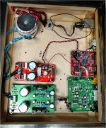
I finally got my copy of the board set up and playing. I've got version 1.07. The power inlet has a line filter built in. I'm using a Kubota psu at =/- 15vdc to feed the board, and a LT1084 psu at 5vdc to feed a wavio usb to I2S board. Only played on optical in so far, I had to fix the source selector switch that came with the board it wasn't set up properly but it's working now. Using slow rolloff min phase reconstruction filter. I let it burn in for a few hours without touching anything, it sounded pretty nice off of the bat. I swapped the I/V opamp out to a LME49720 which resulted in a definite improvement, also swapped in a THS4032, also sounded good but can't really tell if it sounded better than the LME49720. I'll need to listen for a while then swap back to the LME49720. I compared it to two DACs I had in my workshop on optical input. A cheap NOS AD1865 Chinese dac, and a ES9023 based Subbu dac. The ES9038Q2M board was the clear winner, it had a similar family sound with the Subbu, but had a more expansive sound stage, more 3D, more low level detail. I was very surprised. My next step will be to remove the coupling caps, but I need to read up more closely how to adjust the DC offset by adjusting/adding resistors. I also will be testing the wavio input and higher sample rate settings.
Attachments
Put the test perfboard assembly (still with 1st modded dac) into an aluminum case with the lid off. Basic symptoms are about the same as in the steel case, until I start perturbing it mechanically, that is. A little sensitivity to mechanical flexing remains, at the moment more so at the AK4137 board near the clocks. Also, DPLL stability seems better with some loose coupling between dac and AK4137 board clock sections, kind of similar to before but easier to adjust and keep stable. Between loose coupling with my fingers and some minor flexing, tuning of DPLL stability doesn't seem excessively sensitive in the aluminum case.
I still would like to see if I can find out what is happening with that tuning when DPLL is better stabilized. What I am thinking is that I would like to look at the dac clock relative to the incoming DSD clock line on the dac board I2S connector and watch what happens there as I flex and couple DPLL stability into tune. About all it can be is frequency and phase of incoming signals relative to the dac clock. Main question might be on what time frame changes in those variables occur. If they change slowly enough then I might be able to see something on a scope. If they occur entirely as jitter, probably the scope will not be useful.
Also, took another look at the jitter meter on loan from Richard Marsh. I misspoke last time about its resolution, turns out it only goes down to 100pS. Compare that to, say, the 45fS jitter claimed for Crane Song Solaris dac clocking and its easy to imagine why I might not be able to get a good picture of what is really going on with DPLL stability if the only potentially observable change to my tuning perturbations is in some jitter time frame.
Of course, if I understood the tuning phenomenon better then I might be able to rig up something to adjust it into good stability, even with some kind of servoing if necessary. Hard to do though when if no useful means of measurement.
Anyway, I was thinking of configuring the dac chip to output its MCLK signal on a gpio pin and comparing that to the incoming DSD clock. I am further thinking of attaching some ufl connectors to the dac board as scope test points. I don't think I would be able to hold scope probes and fiddle around with loose clock coupling, and maybe a little AK4137 board flexing all at the same time.
Last edited:
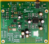
my modification on the 9028q2m boad, all photos are hi resolution, download and zoom it in to see more details.
1st, why 9028q2m?
https://www.diyaudio.com/forums/pc-...-i2s-dac-hats-raspberry-pi-5.html#post5258160
https://www.diyaudio.com/forums/pc-...i2s-dac-hats-raspberry-pi-31.html#post5440848
https://www.diyaudio.com/forums/pc-...i2s-dac-hats-raspberry-pi-32.html#post5441859
taking out the mcu is optional, it's easy to cut anywhere along the red, soldering on yellow.
Attachments
- Home
- Source & Line
- Digital Line Level
- ES9038Q2M Board