Hi Freezebox,
You could put the AVCC divider to make Vref on the output stage board, but I haven't seen any evidence of problems from putting it on the AVCC board. The distance the wires run is not very far, it does not risk contaminating AVCC itself that way, and I put the dac in a shielded steel case for normal operation (which would definitely be recommended for multiple reasons). One could leave the Vref divider on the AVCC board, and just add another RC filter at the output stage board, which I think would make more sense if you want to try something like that. Still don't think it should be necessary though.
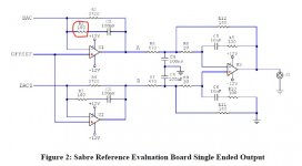
Putting a small resistor in series with the 330pf I/V feedback cap would not necessarily improve RF filtering, and I don't see such a resistor in the ESS schematics I use. What a resistor like that would be for would be to change the frequency and phase response of the feedback network at very high frequencies to keep the opamp stable and free of oscillations and ringing. What is needed there would depend on the opamp, the behavior of the feedback network components at very high frequencies, and whatever else is connected to the opamp input terminals, which in this case would be the high frequency impedance of the dac outputs and wiring that goes to them. When I check the opamp operation with a scope, I am not seeing any evidence that we have a problem of that nature to ameliorate. We could try to model the circuit with spice as best as we can and see what that shows, but we don't have a spice model of the dac. In addition, in case there is some non-critical gain peaking in the I/V at very high frequencies, we have an RC filter to ground that should take care of any left over RF leakage from the dac outputs. We do it again after the differential summing stage and so at this point I feel pretty confident the output stage is doing what it needs to do.
You could put the AVCC divider to make Vref on the output stage board, but I haven't seen any evidence of problems from putting it on the AVCC board. The distance the wires run is not very far, it does not risk contaminating AVCC itself that way, and I put the dac in a shielded steel case for normal operation (which would definitely be recommended for multiple reasons). One could leave the Vref divider on the AVCC board, and just add another RC filter at the output stage board, which I think would make more sense if you want to try something like that. Still don't think it should be necessary though.
Putting a small resistor in series with the 330pf I/V feedback cap would not necessarily improve RF filtering, and I don't see such a resistor in the ESS schematics I use. What a resistor like that would be for would be to change the frequency and phase response of the feedback network at very high frequencies to keep the opamp stable and free of oscillations and ringing. What is needed there would depend on the opamp, the behavior of the feedback network components at very high frequencies, and whatever else is connected to the opamp input terminals, which in this case would be the high frequency impedance of the dac outputs and wiring that goes to them. When I check the opamp operation with a scope, I am not seeing any evidence that we have a problem of that nature to ameliorate. We could try to model the circuit with spice as best as we can and see what that shows, but we don't have a spice model of the dac. In addition, in case there is some non-critical gain peaking in the I/V at very high frequencies, we have an RC filter to ground that should take care of any left over RF leakage from the dac outputs. We do it again after the differential summing stage and so at this point I feel pretty confident the output stage is doing what it needs to do.
Last edited:
Hi Freezebox,
Opamps are not running hot on my new output stage board, in fact they aren't even warm.
EDIT: I do however have the ground return for the external 5v supply down at the digital end of the dac board. That helps keep HF/RF ground currents away from the analog audio end of the board. Also, that is the only ground connection of the 5v supply to dac board, there is no other ground connection between external power supplies, so no 5v ground loops.
Also, the schematic you show was from long ago and for an earlier Sabre dac. It came from an old application note, not a data sheet. The latest evaluation boards use zero ohms in that position.
In addition, the dac output stage schematic that I used as a model for the new output stage did not have a resistor there.
However, you can put 100 ohms there if you want. It would start affecting the frequency response up around 5MHz or so. It might actually reduce RF filtering above that, but like I said, there is an RC filter to ground right after that opamp which should help fix any worsening you might cause.
If we really wanted to investigate this more, we could inject an big enough RF current (to see something at the opamp output with a scope) into the opamp summing junction and sweep the frequency to see what happens. Probably not worth the effort, especially since we have provided sockets so people could swap output stage opamps if they want to try that (not recommended though). In that case, all fine adjustment of RF frequency and phase would be out the window anyway.
Last edited:
Hi Markw4
just ordered a 2nd es9038q2m board (green version) to modify as I am a little afraid of changing something on my current modded board and killing it with no back-up. I also see an option using this 2nd DAC board as DAC when doing digital XO filtering for my 2 way speakers in future (currently its analog active filtered).
Further I would like to have a comparison board to my current board to see if I can further improve SQ by different mods.
I want to do the smd output stage again, using modified onboard circuit as symmetry stage again.
I will use crystek clock this time (instead of NDK Sda), LTC6655 as ref for AVCC and 22uF MKP film caps for AVCC.
Clock, VCCA and DAC power will be filtered with LP5907 LDO, while I feed 5V to the orig. 3,3V powerlines (MCU line keeps orig. 3.3V reg). The 3,3V LDO will be placed where ferrite filters are applied at the moment.
So what I would like to know about your new smd version is, if you will do same circuit as for through hole or any other mods like rasmussen filter or other values for resistors or mlcc? Will you use AD797 this time? Do you have a part list already?
I would like to place europe mouser order within the next days.
Hi
LTC6655 as ref for AVCC and 22uF MKP film caps for AVCC.
What were the improvements ?
Have you tried with others caps ? 47µf or more
it seems to me that tests were made with values higher than 47μf ....
Thanks
Serge
Hi Serge,
I think the trial of Markw4 to use a film cap (sorry, not MKP but MKS) for AVCC is based on the recommendation of the LTC6655 maker to use film cap as output cap for the reference voltage with certain advantages compared with other cap types. So why not try it for AVCC?
The LME49720 as AVCC source is happy with 10uF already acc. to ESS, so 22uF should be fine anyway.
I did not try yet, as my DAC board already had several solder-unsolder procedures to stand, so I am afraid of killing the pads with further trials. My last change of the clock together with the AVCC cap from Aluminum Electrolyt to organic polymer was not so lucky, but still not sure if the cap or the clock (NDK SDA 50MHz which has lower rising time) caused this small reduction of life-likeness..that is one reason I would like to compare with a new modded DAC board.
Serge,
For the ESS recommended opamp AVCC circuit, the output caps should be in the range of 10uf to 47uf. I recently tried 22uf film caps with good results. In combination with the opamp circuit we are using an LTC6655 as a low noise 3.3v reference.
However, when people don't want to go to the trouble of using the recommended opamp circuit, sometimes they just try adding some big caps. The dac boards come with 47uf in parallel with a smaller ceramic cap. If just using caps to make AVCC more stable, it takes much more than 47uf. Adding another 5,000uf or so of low esr caps to each channel is what some people have done.
Also, when people ask what is the improvement for each individual mod, I am reluctant to try to try answer that since it turns out to be a nonsensical question. I tried to explain recently that the recommended physical changes to the dac board are arranged in terms of what is logical to construct in one smaller sub-project at a time, not in terms of independent perceptual improvements to like or not like. Some changes, or so-called mods, may make the dac more resolving, including of its own faults which can make it sound worse until other changes are also made. Such changes are not intended to stand on their own, they are intended to add up to a perceptual improvement only when they all work together. In that sense there is only one recommended mod. It can be done in multiple sub-projects, but it adds up to only one major overall sound improvement for people to judge the perceptual quality of. How does that one big mod sound? It sounds really good, almost great. Good enough to be happy with for many years, I would say, maybe for a decade.
Freezebox,
You probably don't need to worry too much about killing pads. The dac board is only two layer, so one could always drill small holes next to any damaged pads to patch the circuit back together.
In fact, when I removed the nickel pin headers from one AK4137 board recently to replace them with gold plated, I ran into an intermittent problem with two of the pins due to damaged through plating in PCB holes. I just drilled a couple of small holes and patched the traces on top of the board to the bottoms of the new pin header pins using wire wrap wire. It works fine.
It is actually very hard to kill one of the dac boards, only zapping the dac chip itself should be considered fatal to the board. Even losing the MCU would not be the end, since the Arduino we add can program the dac chip for any needed function.
EDIT: Regarding your last clock change, I was disappointed when trying an NDK clock in one of the AK4137 boards. It definitely sounded worse afterwards, more scratchy and distorted. With luck I may have a Crystek to try for that by Saturday, so should find out pretty soon how well it works in comparison.
Last edited:
i thinks you can use a Metal Apple IR remote control (not included) to remotely control your DAC.
Not sure if that is a question. Some ES9038Q2M dac boards at v1.06 or v1.07 can be used with an optional display. The display may be usable with an optical remote. However, since we also tend to use an AK4137 board to drive the dac board, a remote for the dac may be of limited use, but it could still at least control volume.
We also sometimes attach an Arduino to control the dac chip directly. The Arduino could also be made to operate the dac with a remote control of some type. There are libraries for remotes available to help with that.
Last edited:
After a couple of experiments trying alternate clocks for AK4137, looks like the stock 22.579MHz clock that comes with the AK4137 boards may actually be pretty good. I could not improve sound quality with NDK or Crystek clocks, but I could worsen it. Can only assume at this point that since there are many manufacturers of ultra-low phase noise audio clocks down at 22.579MHz, that NDK and Crystek may not lead that particular market segment. Certainly, for a good 100MHz clock for ES9038Q2M, Crystek has proven pretty hard to beat. Not aware of anything better for that. Bottom line is that its probably best to leave AK4137 board clocks alone and only upgrade dac board clocks with Crystek. (Good quality gold flashed or gold plated pin headers and connectors are still strongly recommended for I2S lines.) Those would be the current recommendations, will advise further if any new developments happen to occur. In the meantime, continuing to look into DSP options in the background. Still quite away out on that, so would not recommend waiting for anything there before starting on a project. Sound quality is quite good as is, and happily so. ")
Mark, not sure if this has any bearing on your clock trials for the AK4137 or even if I understand quite what the mechanism is but the info for the cheaper board states...
Both crystals on the board are powered by a precision LDO, and one of the crystals is powered off by the other to reduce interference.
DRONE7,
Actually, that sounds like an incorrect description of how clock switching works. On the more expensive AK4137 board, clocks share a voltage regulator and are switched by using the enable pins on clocks. On the lower cost AK4137 board, each clock has its own dedicated voltage regulator, and the regulators are enabled/disabled. In any case that is not the issue I heard, as I checked for proper clock switching with a scope.
It could actually be that the clocks I tried do have lower jitter than the stock clock, but there may be a complication. Jitter can be random or deterministic, or some mix of both. What a clock's jitter sounds like in a dac or SRC board depends on the its exact structure or composition. None of the clocks we can currently buy has low enough jitter that we can be fully certain its effects are completely inaudible for low phase noise offset frequencies. They can intermodulate down there with audio and we may hear some effects from it if using a very resolving reproduction system. That being the case, the suitability of a particular clock for a particular job may not be entirely determinable from a list of phase noise numbers. They just don't tell the whole story about the jitter's noise/deterministic composition. Probably for very low distortion audio dac design it is necessary to make a short of list of clocks based on published specs then do listening tests to see what audible effects the jitter actually has.
In terms of the foregoing explanation, it could be that the jitter composition of the stock clock was just less objectionable in listening tests, that's all.
For another piece of information in the jitter puzzle, Crane Song says for their latest 5th generation dacs they have some clocks with jitter down at 45fs all the way down to 1Hz!. They currently have the best clocks in the business and they say they don't think the numbers they are getting is the end for jitter audibility, it is only the best they can do for now. (And given how hard it is to get the numbers they are getting, they have been having some problems with clock deliveries due to manufacturing problems. Its very hard to make the clocks meet their specs.)
Looking into to future, some clocks have been developed with jitter down at -130dB at 1Hz offset in university research. We can't buy clocks like that at Mouser yet, but someday when maybe we can we may finally be getting jitter down to as low as where some of the other dac and opamp distortion effects are. Much more likely the clock jitter will actually be inaudible on the best, lowest distortion, and most resolving reproduction systems. For now, we still have to pick some candidates for listening tests, and see which one wins for a particular design. That's my best take on it at the moment, subject to revision of course as any new information comes to light.
DRONE7,
Actually, that sounds like an incorrect description of how clock switching works. On the more expensive AK4137 board, clocks share a voltage regulator and are switched by using the enable pins on clocks. On the lower cost AK4137 board, each clock has its own dedicated voltage regulator, and the regulators are enabled/disabled. In any case that is not the issue I heard, as I checked for proper clock switching with a scope.
It could actually be that the clocks I tried do have lower jitter than the stock clock, but there may be a complication. Jitter can be random or deterministic, or some mix of both. What a clock's jitter sounds like in a dac or SRC board depends on the its exact structure or composition. None of the clocks we can currently buy has low enough jitter that we can be fully certain its effects are completely inaudible for low phase noise offset frequencies. They can intermodulate down there with audio and we may hear some effects from it if using a very resolving reproduction system. That being the case, the suitability of a particular clock for a particular job may not be entirely determinable from a list of phase noise numbers. They just don't tell the whole story about the jitter's noise/deterministic composition. Probably for very low distortion audio dac design it is necessary to make a short of list of clocks based on published specs then do listening tests to see what audible effects the jitter actually has.
In terms of the foregoing explanation, it could be that the jitter composition of the stock clock was just less objectionable in listening tests, that's all.
For another piece of information in the jitter puzzle, Crane Song says for their latest 5th generation dacs they have some clocks with jitter down at 45fs all the way down to 1Hz!. They currently have the best clocks in the business and they say they don't think the numbers they are getting is the end for jitter audibility, it is only the best they can do for now. (And given how hard it is to get the numbers they are getting, they have been having some problems with clock deliveries due to manufacturing problems. Its very hard to make the clocks meet their specs.)
Looking into to future, some clocks have been developed with jitter down at -130dB at 1Hz offset in university research. We can't buy clocks like that at Mouser yet, but someday when maybe we can we may finally be getting jitter down to as low as where some of the other dac and opamp distortion effects are. Much more likely the clock jitter will actually be inaudible on the best, lowest distortion, and most resolving reproduction systems. For now, we still have to pick some candidates for listening tests, and see which one wins for a particular design. That's my best take on it at the moment, subject to revision of course as any new information comes to light.
Unfortunately the clocks you are using (NDK / Crystek) are reportedly all
over the place jitter wise. The word from people that measure them with
phase noise / AV testing gear is if you want actual decent jitter specs, AKA
something close to the Cranesong Solaris clocks then you pretty much have to
measure a bunch and select them.
Better clocks that improve on the Solaris clock specs are available but are generally
SC-cut OCXO which are very expensive.
T
Terry,
If a clock manufacturers can't control specs then that is problem for most people and dac manufacturers in general. What you say used to be true for NDK clocks until they added the A suffix versions with are supposed to have more of guaranteed performance. That is, one could get lucky trying a bunch of clocks and pick the best one(s). However, most jitter measurement equipment most people have access to can't characterize the exact type of jitter down at 1Hz. Even for equipment that can go to down to 1Hz, what one typically gets is some statistical information that still does not tell the whole story about the particular type of jitter to the degree necessary to predict exactly what it would sound like in a particular application without listening. In high end audio design, always best to both measure and listen. Failing to do either can lead to problems.
Also, please see the table on this page: RF/Microwave Low Noise Oscillators
It is doubtful one can hit such numbers simply with single cut crystals because there are various other problems that have to be solved to get phase noise down that low.
Commercially, for single cut oven-controlled it is possible to get clocks such as these which are not available at very high frequencies, are very expensive and maybe not available in voltages we could use: https://www.vectron.com/products/ocxo/ox-204.pdf
Yet, somehow or other companies such as Benchmark Media find some way to make a very good dac in mass production without buying 10 or 100 clocks to get one good one. They have to or they couldn't sell dacs at the prices they do. So, there have to be manufacturers one can work with if buying a lot of parts in order to get clocks that reliably sound good. The other thing to do is successively reduce jitter in stages with the clocks one can actually buy in bulk.
Last edited:
Thought I might mention I have been working on getting a Linux computer set up for working with Xilinx Spartan 6 chips. Turns out the basic free software for working with Spartan 6 is called ISE. It has some facility to create 16-bit FIR filters if coefficients are given to it. The coefficients in turn typically might come from Matlab. Programming a Spartan 6 to do 24-bit or 32-bit filters appears to require some additional resources, or maybe a lot of very low level VHDL type programming, not something that sounds like a lot of fun. Its been a long time since I used Linux, in this case Ubuntu, so I am reacquainting myself with some of it. It is a bit of progress, just slow progress to investigate how Spartan 6 might be used. We know there has to be some way, because Benchmark DAC-3 uses one to good effect. There are various other tools out there besides ISE, but not much in the way of freeware.
In other news, recently received a second low cost AK4137 board, but this one has the high sample rate PCM option, rather than being the standard version. I want to upgrade the output pin header to gold flashed pins and add a couple of extra ground pins. Then it should be about ready for test run with the new dac board.
How are other people doing with their dac builds? Anyone else have any progress to report? We all really like to hear from folks as things move along.
Last edited:
In another thread, cdsgames recently announced that all previous Katana dac reviewers will be receiving a Katana 1.2 dac with the two different output boards and an isolator board. That being the case, we should be seeing some more updated news about Katana v1.2 at some point in this thread.
Initial reviews from people who have already received the new Katana seem pretty favorable. They say sound quality has improved a lot.
What that means relative to our dac modding efforts is that recent Katana improvements should once again make it more competitive in terms of sound quality with our recently improved AVCC and output stage mods. It will be very interesting to see how the next round of listening comparisons turns out, although we can be reasonably certain DAC-3 will always come out on top.
On thing that is not quite clear yet is how good power supplies need to be for optimal Katana sound quality. Also, although Allo is working custom power supplies that could be used with Katana, the power supplies designs are not yet complete. It could be that I will have to do some work with power supplies myself to run the fairest possible listening comparison test. Will have to see on that.
Just tried a brief experiment out of curiosity. Tried substituting one of the LME49720 opamps in the output stage with an OPA1612. Tried first for the differential summing stage, then for the I/V stage for one channel. Preferred the sound of LME49720 in both positions, although in both cases it is a little brighter sounding vs OPA1612 as determined independently by two different listeners. It could be that the OPA1612 sound is actually slightly less distorted than LME49720, but was not set up to check with measurements today. If the difference in perceived brightness does turn out to correlate with measured distortion, then it would appear a tiny bit of distortion might be flattering to the dac, AK4137, and whatever else is there aside from the opamps themselves. Makes me think the nice sound of the dac in its current design iteration may be a bit serendipitous, but that's okay I guess.
In other news, there is an ES9028PRO chip and otherwise unpopulated PCB are on the way from DIYINHK. I decided to go with that rather than a ebay or aliexpress version since I know AVCC will not be tied together for both channels. I want to try some things that I can't do with Q2M and I don't want to be forced into using the higher output currents of ES9038PRO. One of things I would like to try is the double-number-of-taps interpolation filter option although I will probably have to come up with my own coefficients. Also want to see how much effect lower noise associated with paralleling output channels has on sound quality. According to some reports, it can matter a lot. In other words, just some more stuff to experiment with and compare with Q2M which hopefully may be of interest to Q2M modders.
In the meantime, still doing some research into options for making good use of Spartan 6.
While I continue to work at a somewhat slowed down pace on dac-related projects, it sure would be good to hear from people here that someone somewhere is actually starting to make some progress with dac modding. If nobody is, then no reason for me keep posting here.
Seems to me terry22 had clocks removed from both his dac boards and was getting ready to solder his Crystek clock to one of them. MrSlim was nice enough to draw up the latest schematics we have, but I have no idea if he is up for modding a dac or not. Other people talked about starting to get to work a little at a time in order to try to get done by the end of the year, but its already November. That raises the question, before the end of which year? Come on, guys. Is this going to a thread where the most active participants buy a box of parts with good intentions then leave them sitting in back of a closet? If so, then the other guys waiting to hear the first sound quality reports from people other than me are going to be very disappointed. So, please, let us know how things are coming along even if they are delayed a little. What is the current estimate for having a few pics to post of anything? A few strips of copper foil sitting on the bench, really anything, whatever you can find to share. Thank you for stepping up and contributing, whoever you may be. 
In other news, there is an ES9028PRO chip and otherwise unpopulated PCB are on the way from DIYINHK. I decided to go with that rather than a ebay or aliexpress version since I know AVCC will not be tied together for both channels. I want to try some things that I can't do with Q2M and I don't want to be forced into using the higher output currents of ES9038PRO. One of things I would like to try is the double-number-of-taps interpolation filter option although I will probably have to come up with my own coefficients. Also want to see how much effect lower noise associated with paralleling output channels has on sound quality. According to some reports, it can matter a lot. In other words, just some more stuff to experiment with and compare with Q2M which hopefully may be of interest to Q2M modders.
In the meantime, still doing some research into options for making good use of Spartan 6.
While I continue to work at a somewhat slowed down pace on dac-related projects, it sure would be good to hear from people here that someone somewhere is actually starting to make some progress with dac modding. If nobody is, then no reason for me keep posting here.
Seems to me terry22 had clocks removed from both his dac boards and was getting ready to solder his Crystek clock to one of them. MrSlim was nice enough to draw up the latest schematics we have, but I have no idea if he is up for modding a dac or not. Other people talked about starting to get to work a little at a time in order to try to get done by the end of the year, but its already November. That raises the question, before the end of which year?
Come on, guys. Is this going to a thread where the most active participants buy a box of parts with good intentions then leave them sitting in back of a closet? If so, then the other guys waiting to hear the first sound quality reports from people other than me are going to be very disappointed. So, please, let us know how things are coming along even if they are delayed a little. What is the current estimate for having a few pics to post of anything? A few strips of copper foil sitting on the bench, really anything, whatever you can find to share. Thank you for stepping up and contributing, whoever you may be.
Last edited:
Is anyone out there?
Exactly. You can hear a pin drop. Not a good sign.
NO fears. I am progressing slowly now as there is a functioning DAC on hand.
As I progress a couple things, I wanted to have a simpler DAC for video, so I came across this and gave it a try.
NEW HiFi PCM1794 DAC Decoder Module 192k 24bit | eBay
I don't need DSD for video etc. So with the SRC4392 being able to output IIS, I thought I would use it for that and see.
The other thing is that I wanted to make sure that any steps forward on my 9028pro DAC would be a positive because as we've seen, though on paper some thing might be better or so we think, it sometimes is not.
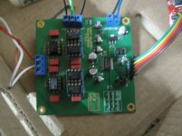
Initially that inexpensive DAC sounded not so good. But I performed some very simple additions by decoupling each PS pin on the op amp with 0.1 and added some bulk caps on the rails. This was done by grinding off some masking on the ground plane and soldering. That was ll the mods performed.
Without the decoupling the sound was very undynamic and thick. No imaging and no depth. This was running with the 5532/34 op amps. Changing to the LME49720/10 op amps immediately made a very noticeable change. Yes, it now sounded brighter as was commented before. It sounded more articulate but it lacked the lower midrange body and there did not appear to have as much energy in the midbass. However it did sound clearer.
Then I changed the differential amp to a AD797. That changed a lot of things, the bottom gained some weight and the sound did indeed smooth out a bit. It did not sound as bright.
Having some dual dip adapters, I hurredly soldered them up and put in an all AD797 system. Then it started to come together. The brightness was now gone, I could listen to this now....and I am not running hot metal domes or ribbons but an older soft dome.
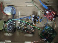
Then as is shown in the pics, it is now running a Jung Sulzer type PS replacing the 317/337 PS I was previously using. This indeed made a large difference. Possibly because the "AVCC" of the 1794 DAC is powered by the same power rails for the op amp. The better regulation possibly helps the LT1761-5 that powers the DAC analog lines.
As it is now, it no more mods except for a possibly better Super Reg for the analog. No need for more as it is destined for video.
So using this, I was able to parallel the same sound characteristics I had found on my 9028pro dac, tells me it is most likely the op amp sound characteristic itself. I have not tested the OPA1612/11 combo as yet. What I do have is a couple OPA1611 op amps on a board running a class A transistor stage output. I might try that this weekend time permitting.
At some point, you get to a stage where if you are happy with it, you need to call it a stop.
Here's my thinking, about the op amps. You can get into a conundrum. Is the OPA1611/12 more accurate? we don't know. So we measure it but what does that tell us? Are we measuring the right parameter? I'm not sure. If mark thinks he prefers the LME49720 in HIS system, then it is more accurate to him IN THAT SCENARIO. It could change with another set of headphones.
As I progress a couple things, I wanted to have a simpler DAC for video, so I came across this and gave it a try.
NEW HiFi PCM1794 DAC Decoder Module 192k 24bit | eBay
I don't need DSD for video etc. So with the SRC4392 being able to output IIS, I thought I would use it for that and see.
The other thing is that I wanted to make sure that any steps forward on my 9028pro DAC would be a positive because as we've seen, though on paper some thing might be better or so we think, it sometimes is not.
Initially that inexpensive DAC sounded not so good. But I performed some very simple additions by decoupling each PS pin on the op amp with 0.1 and added some bulk caps on the rails. This was done by grinding off some masking on the ground plane and soldering. That was ll the mods performed.
Without the decoupling the sound was very undynamic and thick. No imaging and no depth. This was running with the 5532/34 op amps. Changing to the LME49720/10 op amps immediately made a very noticeable change. Yes, it now sounded brighter as was commented before. It sounded more articulate but it lacked the lower midrange body and there did not appear to have as much energy in the midbass. However it did sound clearer.
Then I changed the differential amp to a AD797. That changed a lot of things, the bottom gained some weight and the sound did indeed smooth out a bit. It did not sound as bright.
Having some dual dip adapters, I hurredly soldered them up and put in an all AD797 system. Then it started to come together. The brightness was now gone, I could listen to this now....and I am not running hot metal domes or ribbons but an older soft dome.
Then as is shown in the pics, it is now running a Jung Sulzer type PS replacing the 317/337 PS I was previously using. This indeed made a large difference. Possibly because the "AVCC" of the 1794 DAC is powered by the same power rails for the op amp. The better regulation possibly helps the LT1761-5 that powers the DAC analog lines.
As it is now, it no more mods except for a possibly better Super Reg for the analog. No need for more as it is destined for video.
So using this, I was able to parallel the same sound characteristics I had found on my 9028pro dac, tells me it is most likely the op amp sound characteristic itself. I have not tested the OPA1612/11 combo as yet. What I do have is a couple OPA1611 op amps on a board running a class A transistor stage output. I might try that this weekend time permitting.
At some point, you get to a stage where if you are happy with it, you need to call it a stop.
Here's my thinking, about the op amps. You can get into a conundrum. Is the OPA1611/12 more accurate? we don't know. So we measure it but what does that tell us? Are we measuring the right parameter? I'm not sure. If mark thinks he prefers the LME49720 in HIS system, then it is more accurate to him IN THAT SCENARIO. It could change with another set of headphones.
Attachments
BTW Mark, the SRC4392 HF distortion is a lot reduced with the PCM1794. It is running at 192KHz. Maybe the ESS DAC clash for some reason with it. But in this scenario, it is more listenable.
However on second thought, I never hooked up the SRC4392 via IIS to the 9028Pro.
So many combos to play with.
However on second thought, I never hooked up the SRC4392 via IIS to the 9028Pro.
So many combos to play with.
- Home
- Source & Line
- Digital Line Level
- ES9038Q2M Board