Hi,
Good to hear back that the dac is now working. J3 rather than J2 only means that the firmware was a little different when your's was made.
By the way, the ES9038Q2M is still the same, which means you could mod the dac you have into being a very, very good one as we like to do here.
Mark,
The DAC board says ver. 1.04. I followed just a couple of the mods suggested here such as
- changing the capacitors (2) near the DAC chip to Panasonic 390mf,
- same for the caps near the OpAmp,
- replacing the Am117(?) 3.3v regulator with a discrete one I bought in eBay,
- did opamp rolling ending up with Muses01.
PSU is linear low noise also from eBay. Source player is an old MacBook. I use the Halide Bridge cable for USB-Spdif coax.
It really sounds fantastic on my system, that is for my ear, compared to my Peachtree DAC-it X, and two diy DAC I assembled from Chinese boards bought from eBay (ES9018K2M and ES9028Q2M).
I’m not sure I can implement the more difficult mods suggested and the one currently being discussed. But still looking for opportunities to improve.
I’m not sure I can implement the more difficult mods suggested and the one currently being discussed. But still looking for opportunities to improve.
Not sure what you would consider to be a more difficult mod? Serge put up a pdf for swapping out the clock in his thread and I see some relative beginners were able to follow it and get the dac working with the new clock.
Seems to me anyone who can do that should probably be able to do most mods. The clock is, after all, an SMD part even if not a small one.
It does matter to have a temperature controlled solder iron and multiple sized tips for it, along with some small hand tools. Maybe a head-mounted magnifier of some kind, if like me.
A lot of the rest of it is just confidence that comes from practice. The small stuff can look much harder than it is. Only way to find out is to try it. There are some SMD practice kits available and some youtube videos with helpful advice. May as well give it a try, SMD is a big part of modern electronics and much of it is quite doable at home.
")
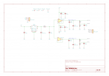
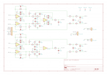
Through Hole AVCC and IV-Output Schematics
I've revised the AVCC schematic to show C8-9 as either Electrolytic or Film, and the board layout will include footprint's for both.
I've also added optional balanced outputs to the IV stage. R50-53 are jumpers that can be left out if the balanced outputs are not required. These jumpers reduce the amount of non-powered wiring on the board that could become antennae for external noise pickup.
Both Sheets of the BOM have been updated, as well as the Combined sheet.
Attachments
MrSlim,
Thank you so much, sir. However, may I request to please revise the balanced outputs to add the circuitry shown below following each unbalanced output, if a balanced option is desired?
Also, not quite clear on why connectors are shown for the inputs, since it is strongly preferred to tie the ground planes together through a continuous bond.
This would be the case for both AVCC and the output stage. Perhaps more critically so for AVCC which needs to be as close to the dac pins as possible with as low a source impedance as reasonably possible.
EDITx: This has already been edited quite a bit, but I would like to add that I include 1,000uf electrolytics in parallel with 1uf film caps at the +-15v power entry point on the output stage board. I tie the AVCC board to the output board with short length 18 gauge wires for +-15v to the output board power entry filter caps.
Attachments
Last edited:
Somewhere or other I would also like to include that I use local 3.3v regulators, LT1763, for clock and VCCA. In part that is to help isolate them from digital noise from the MCU as recommended by ESS.
In addition, since I use an external +5v supply to power all three 3.3v regulators on the dac board, the ground return to the 5v supply is taken from the digital end of the dac board. The idea is to help keep digital ground currents from flowing in the analog sections of the dac as much as possible. +-15 and +5v power supply grounds are only tied together at the dac board.
In addition, since I use an external +5v supply to power all three 3.3v regulators on the dac board, the ground return to the 5v supply is taken from the digital end of the dac board. The idea is to help keep digital ground currents from flowing in the analog sections of the dac as much as possible. +-15 and +5v power supply grounds are only tied together at the dac board.
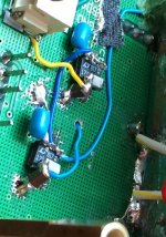
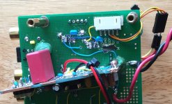
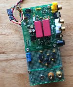
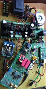
Pulled the dac out of the test box to work on the quality of connections between AK4137 and ES9038Q2M. Trying to get DPLL bandwidth lower requires low connector noise. Will try soldering ribbon cable at AK4137 end, and more connector ground pins at dac I2S input.
Anyway, took the opportunity to take some pics showing the test board and the current state of the dac board including the LT1763 3.3v regulators for clock and VCCA.
Anyway, took the opportunity to take some pics showing the test board and the current state of the dac board including the LT1763 3.3v regulators for clock and VCCA.
Attachments
Last edited:
Both Sheets of the BOM have been updated, as well as the Combined sheet.
Just noticed BOM item 6 shows both 220pf and 220nf. The nf abbreviation should be corrected to pf. Thanks!
EDIT: Also noticed in BOM for AVCC, there are no 10uf aluminum electrolytic. Instead there are five 10uf tantalum caps. The 10uf tantalum caps should be quantity 2, for opamp power decoupling only. 10uf filter caps for 3.3v AVCC and for Vref should be aluminum electrolytic, because tantalum caps are too noisy for that use. So, that would be quantity 3, 10uf aluminum electrolytic (low esr wouldn't hurt but probably not necessary here).
Last edited:
MrSlim,
Thank you so much, sir. However, may I request to please revise the balanced outputs to add the circuitry shown below following each unbalanced output, if a balanced option is desired?
WRT revised arrangement, 33k will generate a lot of noise. Johnson noise alone will be around 33 nV/rt Hz then add current noise of opamp into
33k/2.
T
Hi Terry,
Agreed. That schematic was copied from somewhere else. Makes sense to reduce those resistors to something more reasonable. In case the balanced load impedance is very low, it might make sense for the resistors not be be too small though. Something like 4.7k would probably be okay. Signal to noise by that point should be pretty high anyway. If someone knows they won't be driving a very low impedance load they could make the resistors smaller too.
Agreed. That schematic was copied from somewhere else. Makes sense to reduce those resistors to something more reasonable. In case the balanced load impedance is very low, it might make sense for the resistors not be be too small though. Something like 4.7k would probably be okay. Signal to noise by that point should be pretty high anyway. If someone knows they won't be driving a very low impedance load they could make the resistors smaller too.
Not sure what you would consider to be a more difficult mod? Serge put up a pdf for swapping out the clock in his thread and I see some relative beginners were able to follow it and get the dac working with the new clock.
Seems to me anyone who can do that should probably be able to do most mods. The clock is, after all, an SMD part even if not a small one.
Mark,
I have not done any Smd soldering before, but yes perhaps it is time to try my hands on this. I’ll search for Serge’s pdf on the clock and understand what improvements are to be expected and how to install a new clock.
I read an article reviewing a recently released version 1.07 of this board. Apparently it is a much improved version. But I couldn’t find it in eBay. Was thinking to reapply the mods including the new clock suggested.
Serge's thread is over here: ES9038Q2M Production
You can buy SMD practice soldering kits on ebay, amazon, aliexpress, etc. They mostly don't come with much directions, but if you search for youtube videos there are some good ones.
The new v1.07 boards are available with a display and can work with an optical remote control. However, they cost more with a display and it doesn't help all that much considering the price. If you know you don't want a display there are still 1.06 boards around. We just recommend the green boards over the blue ones which are more cheaply made and are not available with displays. The good thing about having a display, is that it makes it easier to hack into the dac control registers without having to do tricky soldering. Just a quirk of the firmware that makes them that way.
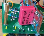
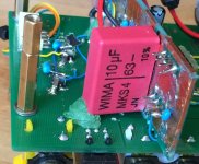
However, I suspect your old board could probably work okay. If you could post pics of the top and bottom in good focus so we can take a look, we could probably give you a better opinion on that.
Also, what type of soldering iron do you have? I used a more or less standard Weller solder station for a long time with a few different tips on hand. If you have a picture or model number that would help understand what type of work it would be okay for.
You can buy SMD practice soldering kits on ebay, amazon, aliexpress, etc. They mostly don't come with much directions, but if you search for youtube videos there are some good ones.
The new v1.07 boards are available with a display and can work with an optical remote control. However, they cost more with a display and it doesn't help all that much considering the price. If you know you don't want a display there are still 1.06 boards around. We just recommend the green boards over the blue ones which are more cheaply made and are not available with displays. The good thing about having a display, is that it makes it easier to hack into the dac control registers without having to do tricky soldering. Just a quirk of the firmware that makes them that way.
However, I suspect your old board could probably work okay. If you could post pics of the top and bottom in good focus so we can take a look, we could probably give you a better opinion on that.
Also, what type of soldering iron do you have? I used a more or less standard Weller solder station for a long time with a few different tips on hand. If you have a picture or model number that would help understand what type of work it would be okay for.
Last edited:
Serge's thread is over here: ES9038Q2M Production
However, I suspect your old board could probably work okay. If you could post pics of the top and bottom in good focus so we can take a look, we could probably give you a better opinion on that.
Also, what type of soldering iron do you have? I used a more or less standard Weller solder station for a long time with a few different tips on hand. If you have a picture or model number that would help understand what type of work it would be okay for.
Mark,
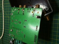
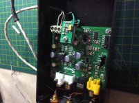
Photos of the DAC. Embarrassing you will see how bad my soldering skill is.. ha ha.
The RCA jacks on the board are bit flimsy so I have a separate set on the plastic chassis.
Attachments
Noise from dac is quite small. Despite 2 stage filtering there is another filter at output. Output load 220R/6,8n is not good for lme49720... of course for my experiences.
Try to filter as much as possible noise before enter the opamp but not load dac too much. This gives me best result at last designs.
Try to filter as much as possible noise before enter the opamp but not load dac too much. This gives me best result at last designs.
Mark,
Photos of the DAC.
The dac board looks like it has the right stuff on it to sound good modded.
In case in helps at all, I wrote some info about soldering before:
https://www.diyaudio.com/forums/digital-line-level/314935-es9038q2m-board-207.html#post5497241
https://www.diyaudio.com/forums/digital-line-level/314935-es9038q2m-board-246.html#post5532704
Cleaning the tip just before heating each joint helps. Use a brass brillo pad type cleaner, such as the one made by Hakko. There are cheap refills available for that type of cleaner, too.
Output load 220R/6,8n is not good...
While I understand the possible concern, I thought about it a lot too. Thing is about a lot of the earlier filtering is that it depends on opamp gain which is falling off as frequency rises, thus the filtering becomes less effective at very high frequencies. In addition, at this point I am not seeing or hearing a problem. Sound quality is better than ever, for one thing. The RF noise is small enough at that point the current flowing into that last filter cap is so small the opamp is hardly loaded. However, a final real pole just before leaving the dac board seems to be best for power amps, at least for mine.
Will you publish a complete BOM soon?
thanx
Hi terry22,
Haven't heard from you for awhile. Don't know if I scared you off with LT1763 modding or not? If so, no reason to give up. I'm sure something can be worked out for beginners that will be satisfactory.
Although I said I was planning to get started on it later, I have started looking into Spartan 6 possibilities. The Chinese Spartan 6 board I have is actually has a little bit more stuff in it than the one in DAC-3. However, DAC-3 has the faster 'speed grade 3' rating. The one I have is 'speed grade 2' and runs on a 50MHz clock.
It turns out there is a freeware version of the old Xilinx Spartan 6 development system software, that is mostly obsolete compared to the newer payware development systems. It also turns out that Spartan 6 is now the bottom on of the line for currently active Xilinx chips.
Xilinx makes some really powerful higher grade chips, and has fancy development software making efficient FIR filter development easy. However, not going to happen because of the high entry cost.
Getting back to reality, Spartan 6 is really designed to be a natively 16-bit part, with 18-bit adders to allow for a little overflow. It can be run at double precision by chaining internal processing units together, at some performance cost of course.
My impression at this point is that it might be possible to make a better 8x oversampling interpolation filter for the dac with a Spartan 6, but maybe only for lower sample rates, say up to 192kHz or so, and most likely using a higher speed grade part than what I have right now.
I have quite it bit more to learn about using the things and designing filters to run on them, but I'm just taking it a little at a time and mulling it over as I go.
---------------
In other news, I did do as I said and drew up a pencil sketch layout of a SMD output stage. It's not legible enough for me to post at this point, but it works with three 8-pin Surfboards of this type: https://www.capitaladvanced.com/pdf documents/9081idsa.pdf
I expect I will probably build one pretty soon to show how it might be done. Since I will have it then, may as well put it to good use by using it to update my 1st modded dac. May I ask if anyone is waiting for the SMD output stage to be completed before starting on dac modding? If I am holding anyone up, I will try to prioritized getting it done sooner rather than later.
Mark,
I have not done any Smd soldering before, but yes perhaps it is time to try my hands on this. I’ll search for Serge’s pdf on the clock and understand what improvements are to be expected and how to install a new clock.
I read an article reviewing a recently released version 1.07 of this board. Apparently it is a much improved version. But I couldn’t find it in eBay. Was thinking to reapply the mods including the new clock suggested.
Buy Products Online from China Wholesalers at Aliexpress.com
Page not found.
Maybe it was something you bought that you had to logon to view? If so, we would need a link to a publicly viewable version.
The dac board looks like it has the right stuff on it to sound good modded.
In case in helps at all, I wrote some info about soldering before:
https://www.diyaudio.com/forums/digital-line-level/314935-es9038q2m-board-207.html#post5497241
https://www.diyaudio.com/forums/digital-line-level/314935-es9038q2m-board-246.html#post5532704
Cleaning the tip just before heating each joint helps. Use a brass brillo pad type cleaner, such as the one made by Hakko. There are cheap refills available for that type of cleaner, too.
Thanks for the soldering tips, Mark.
As you’ve suggested, I need to practice and hone my soldering skill before attempting to do the clock change on my final board.
- Home
- Source & Line
- Digital Line Level
- ES9038Q2M Board