@andora76,
Okay. Whatever works for you is fine with me.
Personally, I am not a believer that solder has a sound.
Regarding the soldering I did on the adapter board, it was the first time I used the new iron tip. The blade of the tip tends to heat the IC pin more than the board which tends to produce solder joints like those shown in the pictures. Soldering with a larger, more traditional tip tends to produce a different distribution of solder more down on the pad, and extending less up the pin. I think the adapter should probably work okay as is, I am not expecting any problems due to the soldering, or due to that the adapter will plug into a socket with spring contacts rather than being soldered to the AVCC board.
No problem you will find out one day. ")
I found in my projects with es9018 ... Avcc and Vref
*22-47uf Vref cap near opamp. Use 1uf smd 1206 + 10nf 1206 pps ECHU under the board and on top 10uf tantal, smd 1206. Highs are less harsh and microdinamics and details are brilliant, excellent. Middle range....better saying 6khz-10khz ...for me, nasty harsh spekter is not so pronounced.
Try to use PPS or mkt ( red wima is little softer) or MKP on analog supply lines ...also in es9018 3,3V AVCC supply. Ceramics sounds thin...plastic, no emotions in music. *
Blue Polymer above are much more harsh than red FP, that was written a lot at subbu dac thread. Avoid this cap if you have filing that midrange becomes annoying, bass did loose weight and highs are plastic and thin with less weight and *quick-ended*.
If this will help you ok, if not skip and go on with mods that you like.
At last shipment from allo we also order Boss dac and digione signature. Es9038q2m beat this dac in no time. Boss plays between speakers, artificall, clean sound and some tension between instruments. Es9038q2m 30% bigger sound lower bass, more emotional, smooth, colorfull. Boss sounds washout, as all 5xxx familly of dacs that i tested till now.
Yes of course in testing phase that is optimall but later when you deceide for best one you solder it directly into pcb.
Attached below is a picture if the inside of Benchmark DAC-3. It sounds very good, better than any other Sabre dac I know of. Thing is, there are no exotic, brand name caps in there, although I am sure they are very good caps that have passed testing to make sure they do not adversely affect sound quality.
Also, in my own experiments I have found that a lot of other things matter more than capacitor brands in most cases. AVCC may be special, but for the most part other aspects of circuit design seem to have more influence over sound quality. However, if one just tries swapping caps and opamps, then that might lead to a different impression of what matters most.
Also, in my own experiments I have found that a lot of other things matter more than capacitor brands in most cases. AVCC may be special, but for the most part other aspects of circuit design seem to have more influence over sound quality. However, if one just tries swapping caps and opamps, then that might lead to a different impression of what matters most.
Attachments
Parts arrived, so back to modding today.
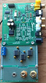
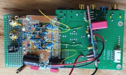
A couple of pics below showing how things are coming together. The AVCC board still needs to go in, and I am thinking about how to position it maybe a little differently this time. In case I need to solder ground plane in the area where the 3.3v bus crosses under some signal traces, I replaced the crossover trace on the bottom with a yellow jumper wire on top. Also soldered on are the dac output wires going to the output stage board, since those solder pads may not be as easy to get to soon.
The second picture shows how it will look with two 22uf film caps on top of the board with leads going down through the original AVCC cap holes (ground end leads will go through new holes drilled in the board where the original output stage was). In addition, outlined in red is where the output of the 5v regulator was lifted so I can bring in external 5v power. That's what the red and black wires coming out from the side are for.
Attachments
Last edited:
ES9038Q2M "Green" vs. "Blue"
just FYI:
have now the 2 here, the "Green"-PCB is thicker, about 20% more in weight, and has a much better "ground/floor"..
overall much more "hi-fi", would say 10-15% difference (better)(the "Green" one)
but many many thx for all the wonderful comments/posts and experiences shared here !!
just FYI:
have now the 2 here, the "Green"-PCB is thicker, about 20% more in weight, and has a much better "ground/floor"..
overall much more "hi-fi", would say 10-15% difference (better)(the "Green" one)
but many many thx for all the wonderful comments/posts and experiences shared here !!
Last edited:
Hi sfb2,
Not sure if you have commented recently, but good to have you participating here today. We hope more people will choose to actively participate if they think they might like to.
With regard to green and blue boards, to me it seems like both sound pretty bad without any mods. If you think either one sounds good or okay now, you might be very surprised at how good they can sound with a full set of mods. May I ask if you have any interest in modding one of the boards yourself, or maybe you have already tried it? You would probably be very happy with the results if you haven't tried it yet.
Regarding the comments and information shared here, I think we try hard, I know I do, to make this the best place for information on getting the best sound quality out of ES9038Q2M dacs. If there is a better place where people share more quantity or quality of useful information for getting best sound quality we would certainly like to know about it.
EDIT: One important difference between the green and blue boards from the perspective of modding that we only recently came to fully appreciate is that it is much easier to do a basic I2C mod on the green boards, whereas the with the blue boards there is no alternative to pin-lifting or cutting into small traces and soldering on wires in order to access dac chip registers for adjustments to optimize sound quality.
Last edited:
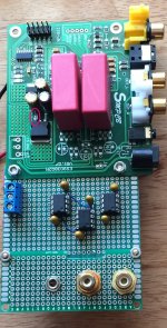
UUU this Wimas are big. They cover half of a dac. Why not solder them under. You have still place for mods on upper part. If you use Wima than unsolder ceramics and use film cap.
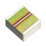
Maybe for those who wants smaller smd size of 22uf film cap
Rubycon PML...seeen on Allo products. Also excellent.
Maybe for those who wants smaller smd size of 22uf film cap
Rubycon PML...seeen on Allo products. Also excellent.
Attachments
@terry22,
Yes, I think that cap should work okay. I am planning to experiment with a different cap, in case you want to wait and see how that turns out, but probably not necessary. I am not expecting much if any difference. More along the lines of just checking to make sure.
Also, an updated BOM will be finished at some point although the one we have now is mostly good. The only issues I am aware of are the 47uf cap that you are asking about, and that an AD797 should not currently be included.
Thank you Mark.
I think I can wait for your upgraded BOM and your final instructions,
I will be more comfortable.
hi,Regarding the comments and information shared here, I think we try hard, I know I do, to make this the best place for information on getting the best sound quality out of ES9038Q2M dacs. If there is a better place where people share more quantity or quality of useful information for getting best sound quality we would certainly like to know about it.
many,many thx Markw4 again, for answering and make this thread/topic so great !! ;-)
all what i now can say is that i´m absolutely happy with the Green one ("Stock")(this hardware-modding is too complicated for me, have absolutely not the skills for that..)by that one interesting fact is maybe that the AD797s are on the Blue the best choice whereas on the Green they are a little bit too thin/harsh..
so u see, and as u posted a lot of times before, it depends all on the unique layouts/builds !!
but many,many thx again for all your wonderful posts !!
Last edited:
UUU this Wimas are big. They cover half of a dac. Why not solder them under. You have still place for mods on upper part.
Maybe for those who wants smaller smd size of 22uf film cap
Rubycon PML...seeen on Allo products. Also excellent.
The reason the caps are on top is because I wanted to keep lead length to a minimum and that could best be done from the top. After all, this is just a test and I want to give them a good chance of showing they can do something useful.
Regarding Rubycons, they are not the same dielectric as Wima. Rubycon uses a an acrylic plastic, IIRC. Also, they are low temp so careful soldering is a must.
EDIT: Just checked and largest value is 22uf, which is good. However, Digikey stocks 0 in large sizes, which is bad. Minimum order is 200 caps, also bad for us, but maybe not for Allo. Mouser does not carry at all.
Allo uses super caps along with the Rubycon films for Katana, which might be another possible solution for AVCC. But, we have a solution that works and rather than spending time on refining it or trying other approaches we probably should be looking, as I keep saying, to things we are ignoring, or whatever is weakest in our current approach. Mostly that seems to be making the mods so people will be willing to try modding at all (which I consider to be a problem that needs attention).
By the way, I don't have any reason to think film caps are going to help anything, its just a random experiment because I feel like it. Might get lucky, or maybe nothing happens. We'll see.
Last edited:
I need help
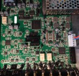
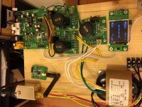
Today I received my powersupplies and fitted all together with the v1.07 Board. But no input signal is detected. I use +-15V and the J6 is open. I testet with the BT i2s, coax and optical. No input signal on the display and no sound on the headphone and the lock led stays dark.
What could I have forgotten?
Attachments
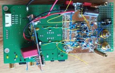
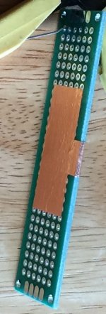
Mounted the AVCC board again, somewhat differently than before (as can be seen in the pics below).
Aside from the location relative to the dac board, there is no epoxy holding down the AVCC board this time. Rather, I removed a patch of solder mask from the dac board ground plane a little less wide than the spacing between the AVCC cap mounting holes, then tinned the area, and then removed excess solder.
I prepared the AVCC board by wrapping copper foil around the edge of it with the intention of soldering the edge to the dac ground plane. Soldered it down to the dac board along both sides of the AVCC board edge using a wide, flat solder iron tip.
Only a few more wires left to connect
Attachments
Last edited:
Hi Mike,
Yes, absolutely. Because Sabre dacs use ASRC to remove and reduce any incoming jitter, the primary clock that matters is always the dac clock.
ESS has some info about how it works on their downloads page here: http://www.esstech.com/files/4614/4095/4305/about-jitter.pdf
Using ESS terminology, the XMOS board clock would be considered the 'transport' clock.
Today I received my powersupplies and fitted all together with the v1.07 Board. But no input signal is detected. I use +-15V and the J6 is open. I testet with the BT i2s, coax and optical. No input signal on the display and no sound on the headphone and the lock led stays dark.
What could I have forgotten?
Hi Bih, I see you are using optical in, have you tried any other inputs?
Can't tell from the picture, but have you modded your board at all and or made any changes since the last time you tried it?
Do you need to remove any jumpers if using the remote to select the input?
Do you have a scope of any kind?
EDIT: Just noticed it looks like both LEDs are lit up in the pic. Are you sending DSD? If not, that might indicate a configuration error or maybe boot error. If using a LDO 5v power supply with a larger than 4.7uf Cset, there could be a problem with the rate at which the 5v supply comes up to full voltage.
Last edited:
Hi Mark
I tried all inputs, no result. There are no mods made. First I will check to bring it up, before I do some mods. The leds are dark. I tried from a CD-Player with coax and optical. Also from a csr8675 bt I2S source. The 5V is made from the board. The startuptime of the powersupply is about 3 sec. Could this be a problem?
To morrow, I will check all the power rails an make perhaps a start speed mod on the LT3042 boards.
To test the 5v start up time theory, you could unsolder or cut the incoming power lead, then turn on the PS first, then connect the wire suddenly like a switch. If 5v is made on the board, you could also lift the output pin of the 5v regulator, patch in a wire maybe with an inline switch or just leads you can twist together, then reconnect it suddenly after the power supply voltage has stabalized.
You didn't say if you have a scope, in case of some other cause?
EDIT: Another easy thing to try would be to unplug the display, and try configuring it with jumpers instead. Just in case it doesn't turn out to be a slow startup problem.
You didn't say if you have a scope, in case of some other cause?
EDIT: Another easy thing to try would be to unplug the display, and try configuring it with jumpers instead. Just in case it doesn't turn out to be a slow startup problem.
Last edited:
Today I received my powersupplies and fitted all together with the v1.07 Board. But no input signal is detected. I use +-15V and the J6 is open. I testet with the BT i2s, coax and optical. No input signal on the display and no sound on the headphone and the lock led stays dark.
What could I have forgotten?
on 1.07 board with a display, J1 and J2 short works for me. lock LEDs remain dark.
on 1.07 board with a display, J1 and J2 short works for me. lock LEDs remain dark.
BINGO!
Thanx
Do you need to remove any jumpers if using the remote to select the input?
About like one of the possibilities I mentioned. Guess I didn't get the wording quite right for it to click.
- Home
- Source & Line
- Digital Line Level
- ES9038Q2M Board