The discussion over the ADA4898 has indicated to me that the aim here isn't to get the best sounding design. Rather to get the best measuring design with the best possible sound.
Could we say that it isn't to get the best sounding design, but the get the best sounding accurate reproduction as the first problem to solve?
It is the same idea with using discrete opamps. The point was and is that one can't make a DAC with remaining implementation problems into a good DAC by adding a little good sounding distortion. OTOH, if you can make a good, well-implemented DAC then let's see that first. If you want to change it or experiment from there that's fine. Otherwise you will never get close enough to find out what good and accurate at the same time sounds like.
In addition, although it may not matter to some, good sounding and accurate at the same time has it's practical uses. Good for mastering for one thing. Good for listening and also good as part of a test system.
But, Hey, I have had my say and made my points. I have showed people how to make a good and accurate DAC. If people don't want that then fine, but that is what I was trying to make possible for anyone that wants it. It sure didn't seem to be possible to do with an ES9038Q2M before. I also tried to get people motivated to give it a try and to work together to make progress on one shared goal. But, I don't want to hang around here to interfere with people who want to do other things. The information is available for anyone who wants it. Below is a summary for anyone who may be interested, then I think I will give it a rest.
page
20 - I started commenting back around there
38 - started posting photos of the modded DAC board
http://www.diyaudio.com/forums/digital-line-level/314935-es9038q2m-board-38.html#post5377834
63 - Post #621 - Pictures and initial description of headphone amp mods
http://www.diyaudio.com/forums/digital-line-level/314935-es9038q2m-board-63.html#post5402398
72 - Post 716 - Pin Lifting
http://www.diyaudio.com/forums/digital-line-level/314935-es9038q2m-board-72.html#post5408825
100 - Post #995 - THD Test results -120dB for DAC, and -105dB for headphone amp
http://www.diyaudio.com/forums/digital-line-level/314935-es9038q2m-board-100.html#post5430064
130 - Post #1300 - Clock removal and replacement
http://www.diyaudio.com/forums/digital-line-level/314935-es9038q2m-board-130.html#post5446706
135 - Post #1343 - Comments re LT3045 Ultra-low 1/f noise supply using LT6655
http://www.diyaudio.com/forums/digital-line-level/314935-es9038q2m-board-135.html#post5448581
165 - Post #1648 - Latest Test setup Picture
http://www.diyaudio.com/forums/digital-line-level/314935-es9038q2m-board-165.html#post5477499
Last edited:
Could we say that it isn't to get the best sounding design, but the get the best sounding accurate reproduction as the first problem to solve?
Its your project Mark, you get to say what the aims are
") I'd interpret the above as what I originally wrote seeing as, by observation, 'accurate reproduction' is resting on THD measurements by and large in this case.
I'd interpret the above as what I originally wrote seeing as, by observation, 'accurate reproduction' is resting on THD measurements by and large in this case.It is the same idea with using discrete opamps. The point was and is that one can't make a DAC with remaining implementation problems into a good DAC by adding a little good sounding distortion.
Perhaps you weren't aware that Samuel Groner designs and markets discrete opamps? I doubt he'd agree that their purpose was to add some 'good sounding distortion', rather his designs address one or two technical weaknesses in standard monolithic opamps without detriment to measurements (other than input offset voltage which isn't too relevant to audio IMO).
Analog Circuit Design · Samuel Groner · Resources · Discrete OpAmps
Things sure get taken out of context. Chinese DACs marketed with fever sound discrete opamps are not using Samual Groner devices. In addition, my previous comments still stand, for someone who has never made a good sounding and accurate DAC how about just doing once as ESS recommends. If you can do that and after hearing it you want want to experiment around then fine. At least then you would be better positioned to know if you were really making things better or worse. I promise you it is easy to get off track and think you are making something better when in reality you are putting a bandaid on a a problem that would be better fixed correctly at the source.
Good night, gentlemen.
Good night, gentlemen.
Things sure get taken out of context. Chinese DACs marketed with fever sound discrete opamps are not using Samual Groner devices.
My apologies, I had indeed missed that piece of context.
As for following ESS's recommendations - the note you shared a few pages back included a couple of (IMO) fairly significant oversights indicating to me that ESS's design suggestions are a long way from being infallible guides to best practices. If anyone's interested I'll point them out.
Last edited:
As for following ESS's recommendations - the note you shared a few pages back included a couple of (IMO) fairly significant oversights indicating to me that ESS's design suggestions are a long way from being infallible guides to best practices. If anyone's interested I'll point them out.
yes, please share your concerns
Here are three snippets where I'm of the view there are worthwhile improvements to be made:
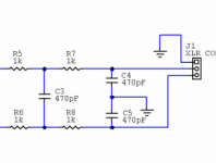
In the first, the output impedance (2k per leg) is rather too high for driving a cable.
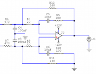
In the second, the input impedance of the bal-SE stage is too low (presumably for noise purposes) and the output padding resistor is missing.
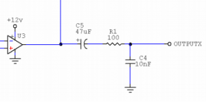
In the third, there's no R to 0V to establish a DC bias across the output 'lytic.
In the first, the output impedance (2k per leg) is rather too high for driving a cable.
In the second, the input impedance of the bal-SE stage is too low (presumably for noise purposes) and the output padding resistor is missing.
In the third, there's no R to 0V to establish a DC bias across the output 'lytic.
Attachments
Hey abraxalito
I really appreciate the suggestions you've made. In the third illustration. I see the tail end of the single op amp IV circuit that ESS recommends. I built it intending to see how it would sound compared to the 3 op amp just so other builders would know. As you pointed out, it didn't work at all and the fault was clear to you but I don't have your knowledge and abilities. In the end my searching for a build fault of my own ended up with me making a mistake and shorting the power pin and AVCC out with my meter tip with the resultant 12V delivered to AVCC which meant instant death to the DAC chip.
Markw4, looks like I was right all along. The circuit that ESS provided is indeed missing something. An EE would have caught it but I had no chance. As it happens my last PM to Markw4 warned him that I was sure that the schematic that ESS put out was incorrect as I checked over 10 times at different periods to see what I might have done wrong and could not find any fault. If there was an error, then someone should also try it and point out the error to potential builders using ESS recommended circuits. We owe future builders that.
The other thing about hat document that ESS put out is the date. Since then many newer LDO regs have been put made. The ESS9008 referenced in the PDF when I checked goes back nearly a decade ago so time has passed but keep in mind the fundamentals of what needs to be done is the same. So the paper is still valid in most ways and it is indeed interesting to see that products ten years after it was known how to do it right is still not being done right...Reason? Must be cost and complexity and the realities of the marketplace.
I am in the inkjet printing business and despite Canon and Epson being large companies with great engineers you sometimes see them making errors. It happens.
Last edited:
Guys, please.
abaraxalito, you make some valid points, don't know why you didn't bring them up before. The resistor to ground to define the voltage on one end of an electrolytic cap came up before and I explained why one might be put in that type of location, but speaking generally not with respect to that particular schematic.
Also, with respect to your comment about the second schematic, if you are referring to the 20 ohm resistor being too small then it isn't necessarily a problem if you see how that part of the circuit works. The current through that resistor is only for very high frequencies and because the amplitude at those frequencies is low, the amount of current needed from the opamp output though the 20 ohm resistor may be well within the capabilities of the opamp to deliver. It depends on how much HF is coming out of the DAC outputs, something that ESS would presumably know.
Mikett, please don't jump to conclusions. An EE would know a missing resistor there would not explain your circuit failing to work at all. It could cause a little 2nd harmonic distortion to appear until the cap self-biased to an appropriate voltage level. To explain further, an electrolytic behaves something like a diode in parallel with a capacitor. If the diode is biased off then no current flows through it. If the diode is not biased off then some current will flow through it on every half-cycle until it is charged up and the diode is biased off (or perhaps until the cap self-destructs from over-current, a very unlikely event in this case). It may leak down, but it would pump back up again with some signal across it. Missing resistors of that circuit function occur with come frequency in things like guitar pedals and they do not damage opamps or cause complete failure of a circuit to operate. You might even like the little bit of even harmonic distortion it can produce. However, for Hi-Fi I would recommend to put the resistor there as it could cause the circuit to measure as having more distortion even if you liked the sound it gave.
Since we have discussed the first two schematic pictures may as well talk about the first one. Yes, the output resistance is 2k per leg on a balanced circuit. Long twisted pair cable typically has a characteristic impedance of around 120 ohm, although not always. Standard impedance for terminating line level professional audio balanced lines is 600 ohms. So, it is clear at a glance the output is not intended to drive long lines or heavily loaded lines. However, it should probably be fine for typical cable lengths connecting a DAC to a power amp with balanced inputs in a home environment. The the power amp had a 600 ohm termination it would cause a volume drop due to voltage divider action which might or might not be an issue.
Obviously, I can't anticipate every problem every single person could have with every single circuit depending on how it is being used. I do encourage people to post schematics and pictures along with a written description if they need help.
Also, I would like to remind people to try not to jump to conclusions. The human brain does it automatically, but often in error, so one kind of has to be on guard for it. If there is a concern as in Mikett's case that an issue is noticed with a schematic, probably better to ask if it would make sense that it could cause circuit operation to fail completely.
Also, a very cheap oscilloscope, even the $20 - $50 kind can be helpful to see what is going on with a circuit that doesn't work. Even without that, troubleshooting steps could be walked through. If somebody says as circuit didn't work and so they gave up on it, there is no opportunity to help with the troubleshooting which might have found the problem, we just don't know.
With regard to my reaction to criticism last night, it was not in isolation. I am getting to the point of wondering if I have been repeating myself too much as of late in this thread and thinking I probably ought to back away, clear my mind on it, and rethink where to go from here if anywhere. Like I said recently, maybe I need to learn how to use the current PCB layout tools since no volunteer has shown up to help with such a project. What keeps me coming back as of recent is there are still too many technical misunderstandings which will lead back to the mix of real information and incorrect information the was here before and that exists in many of the threads in the forum. On the one hand I guess it doesn't matter if people are having fun. On the other hand, there might be some benefit from more actively trying to help people develop better understanding of technical issues. BTW, I have my limits too. EE is a huge field and nobody is expert on everything, and nobody doesn't make mistakes now and then either.
Last edited:
Hey abraxalito
I really appreciate the suggestions you've made. In the third illustration. I see the tail end of the single op amp IV circuit that ESS recommends. I built it intending to see how it would sound compared to the 3 op amp just so other builders would know. As you pointed out, it didn't work at all and the fault was clear to you but I don't have your knowledge and abilities. In the end my searching for a build fault of my own ended up with me making a mistake and shorting the power pin and AVCC out with my meter tip with the resultant 12V delivered to AVCC which meant instant death to the DAC chip.
Markw4, looks like I was right all along. The circuit that ESS provided is indeed missing something. An EE would have caught it but I had no chance. As it happens my last PM to Markw4 warned him that I was sure that the schematic that ESS put out was incorrect as I checked over 10 times at different periods to see what I might have done wrong and could not find any fault. If there was an error, then someone should also try it and point out the error to potential builders using ESS recommended circuits. We owe future builders that.
The other thing about hat document that ESS put out is the date. Since then many newer LDO regs have been put made. The ESS9008 referenced in the PDF when I checked goes back nearly a decade ago so time has passed but keep in mind the fundamentals of what needs to be done is the same. So the paper is still valid in most ways and it is indeed interesting to see that products ten years after it was known how to do it right is still not being done right...Reason? Must be cost and complexity and the realities of the marketplace.
I am in the inkjet printing business and despite Canon and Epson being large companies with great engineers you sometimes see them making errors. It happens.
Absolute Maximum Rating for
Avcc L R,Vcca,Dvcc is 4.7v
Also, with respect to your comment about the second schematic, if you are referring to the 20 ohm resistor being too small then it isn't necessarily a problem if you see how that part of the circuit works. The current through that resistor is only for very high frequencies and because the amplitude at those frequencies is low, the amount of current needed from the opamp output though the 20 ohm resistor may be well within the capabilities of the opamp to deliver. It depends on how much HF is coming out of the DAC outputs, something that ESS would presumably know.
No, I wasn't focussing particularly on that resistor, rather considering the circuit as a whole. In context its not fed direct from the DAC chip, rather from I/V opamps which in turn are fed from the DAC.
I just put the schematic into LTSpice which confirmed my suspicions - that those particular resistor choices place undue loading on both the I/V opamps (not shown in my clipping) and the opamp which is shown in the schematic.
By my estimation, the Zin at the inverting leg (the input impedances aren't equal) is 376ohms. The loading on the opamp shown is around 4dB lower, say 237ohms.
I speculate that the designer may have been aiming for a 600ohm Zin on both legs by the resistors chosen (470+140) but was unaware that there was an imbalance between the two legs. He was also I suspect blissfully unaware of the heavy loading on the output of the opamp shown.
Last edited:
abraxalito, as you have the simulation tool running, could you please check what would be adequate resistor values for this circuit in case of an LME49720 opamp?
Would be also interesting to see your simulation circuit in LTSpice to make my own simulations (I did just discover Spice last week-end, but not sure how to simulate this circuit correctly..)
Would be also interesting to see your simulation circuit in LTSpice to make my own simulations (I did just discover Spice last week-end, but not sure how to simulate this circuit correctly..)
This interesting because the values shown on the ESS circuit is near identical to the one contained in my Ebay 9028 PRO DAC board a the last stage.
On another board the similar circuit is as shown in the attachnment. This board however does not allow for an XLR output.
So is this because one is trying to provide both XLR and Balanced and one dedicated single ended?
This is a good discussion of which might be better considering that the needs for balanced and single ended must be met.
I had been wondering about the values chosen by ESS versus another design and using the same op amps and functionality and what the tradeoffs were.
Attachments
I just put the schematic into LTSpice which confirmed my suspicions - that those particular resistor choices place undue loading on both the I/V opamps
What do you mean by undue loading? Current limiting on the peaks?
- Home
- Source & Line
- Digital Line Level
- ES9038Q2M Board