The upsampler in Reaper DAW is pretty good if set to 'Extreme High Quality, and with dither enabled. It is around -140dB distortion, but even at that there is some audible group delay sound. And of course, that SRC quality on a general purpose CPU is slow and can't be done in real time. It takes dedicated DSP hardware for real-time SRC performance at that level. No upsampler of any kind I have heard can match AK4137 at maximum sample rate.
Mark, what is audible group delay sound?
The benchmark on upsampling would currently be HQplayer and it does real
time upsampling to any format you desire including 8 x DSD if you have the
CPU horsepower - *but it is not that cheap.
Reaper doesn't seem to have changed upsampling wise for quite some time
from what I can tell but it's a great program. You could also use an upsampling 'plug in' in Reaper.
I'm surprised the AK4137 is that good. For PCM -> DSD and DSD -> DSD it
is pretty average and not close to HQplayer. No info on jitter rejection and
one user claims it actually to be poor WRT jitter perfrormance (Mike / Mivera
Audio) but not sure what his testing involved.
One option is to use HQplayer as a benchmark to compare the hardware
based upsamplers to.
WRT any of these upsamplers improving transition band as mentioned in a
previous post - this is not the case. The brickwall filter location is defined
by input sample rate and you can't avoid it. If the IP sample rate is 44.1k
there has to be a LPF at 20kHz regardless of how high it is upsampled to.
T
Group delay is the rate of change of phase shift with respect to frequency. It can be audible
AK4137 may not be great for jitter reduction, don't know. However, it may not matter if it is used as an SRC immediately after and XMOS or Amanero USB board. The jitter is already not bad so no need to improve it. That's the way I am using it. The good thing about using AK4137 is that SRC distortion is down between -140dB to -150dB. That's actually very, very good. The only thing I have seen so far that is as good or better in terms of SQ is the software resampler Weiss Saracon. But it is not real time, and it is very expensive.
HQPlayer is something I haven't tried. Seems unlikely it can be that good if it runs in real time on a PC, but maybe it is. I would have to take it for a test drive to form an opinion.
WRT any of these upsamplers improving transition band as mentioned in a
previous post - this is not the case. The brickwall filter location is defined
by input sample rate and you can't avoid it. If the IP sample rate is 44.1k
there has to be a LPF at 20kHz regardless of how high it is upsampled to.
Actually, the filter that had the be there was the analog one before the A/D converter when they recorded the music. There is no reconstruction filter after that until you get to the DAC or you have to downsample. No filtering is required prior to upsampling.
Anyway, the idea is that virtually all of reconstruction filtering is now done digitally. We don't want to hear the sound effects of any of the reconstruction filters we have to choose from by using jumpers, or however. To avoid hearing artifacts of the digital reconstruction filters we can use the one with the least artifacts, but for it to be the least we need to upsample first.
Now, that's not all that is going on, I am sure. Because to do that trick we only need to upsample to 96kHz for a CD. There is something else going on that make upsampling to very high sample rates sound better and I have not pinned down exactly what it is. Benchmark and Crane Song only support up to 192kHz or low sample rate DSD. For their method to work they upsample to 211kHz which is high enough. But they do some other tricks to with Sharc DSPs with interpolation filtering. One thing they do is prevent intersample overs from occuring during SRC by allowing for more headroom in the calculations. They also allow an extra 3.5dB before going into the DAC chip to prevent ASRC or other intersample overs there. DAC-3 sounds very clean and natural, with extremely detailed sound, but no extra brightness or fatiguing effects. One thing I know they do is use lower frequency clocks with the DACs. No 100MHz clocks, as they are not needed if not going above 192kHz and if using a lower frequency clock it is possible to get lower jitter. That may be some of what is going on with real high sample rates and AK4137, there may be some moderating effect on jitter, which might not be necessary with a lower frequency lower jitter dac clock, but I can't prove that. I don't have the test equipment to look into it.
Last edited:
DVDD supply updated
The DVDD of 9038Q2M is supplied by an internal regulator from DVCC. The 4.7 uF XR5 decoupling capacitor (recommended by ES) is in place now. I removed the original cap close to the leg of DVDD pin (the original cap measured about 80 nF) and all the surroundig stuff. This simple tweak is highly recommended....
The DVDD of 9038Q2M is supplied by an internal regulator from DVCC. The 4.7 uF XR5 decoupling capacitor (recommended by ES) is in place now. I removed the original cap close to the leg of DVDD pin (the original cap measured about 80 nF) and all the surroundig stuff. This simple tweak is highly recommended....
Attachments
Last edited:
Regarding the DVDD cap, they say the reason for using 4.7uf is to make sure there is always at least 1uf there (presumably given that X5R capacitance varies a lot with temperature and voltage). Right now my board has a tantalum and a ceramic. Not sure if that is a problem since there is also an external regulator there too. Even without the external regulator, with the tantalum and ceramic together there is probably 1uf there all the time isn't there? Again, presumably the reason for a minimum of 1uf could be to assure stability of the internal regulator. They don't say a tantalum shouldn't be used in parallel with a smaller ceramic, a common approach for bypassing. Normally the reason for using an X5R, 6.3v cap is because of the small size, not because it is an especially good cap otherwise in almost any way.
Also, with an external regulator, the internal one is likely biased off. In that case what the internal regulator needs for stability might not be as important as what the external regulator needs.
In addition, in regard to the internal regulator I wonder if that was done primarily to make it more competitive for cell phone usage? Having to add an extra power supply next to the dac chip in a cell phone might be a deal killer.
Anyway, to cut to the chase may I ask if you noticed any sound difference after removing the tantalum and existing ceramic and installing the new cap?
Last edited:
Group delay is the rate of change of phase shift with respect to frequency. It can be audible
AK4137 may not be great for jitter reduction, don't know. However, it may not matter if it is used as an SRC immediately after and XMOS or Amanero USB board. The jitter is already not bad so no need to improve it. That's the way I am using it. The good thing about using AK4137 is that SRC distortion is down between -140dB to -150dB. That's actually very, very good. The only thing I have seen so far that is as good or better in terms of SQ is the software resampler Weiss Saracon. But it is not real time, and it is very expensive.
HQPlayer is something I haven't tried. Seems unlikely it can be that good if it runs in real time on a PC, but maybe it is. I would have to take it for a test drive to form an opinion.
Mark, most ASRC's will do at least -140dB distortion.
You can check out a bunch of Software SRC's here:
SRC Comparisons
HQplayer (Sygnalist) does better than -180dB distortion. It is indeed very good and better than any chip based ASRC. That was the whole idea of it - to use the huge processing capabiltiy of a computer to upsample
to say 384kHz or DSD512 with very high quality and then the DAC's internal filters can be switched off / bypassed.
Ironically before Dustin Forman designed the Sabre all-in-one-DAC, he actually started with an ASRC chip and was showing it's performance here. Eventually ESS decided that they would wrap everything in one package and it never got released but here is an FFT of that ASRC's performance which I presume is same as that inside the DAC.
http://www.diyaudio.com/forums/atta...91d1162613209-jitter-blocking-fft_results-zip
Looks pretty good to me
")
WRT group delay - ALL of these ASRC's and software SRC's have zero group delay variation with standard (non min phase) filter in the audio pass band as can be seen at the phase plots here SRC Comparisons
Mark, most ASRC's will do at least -140dB distortion.
WRT group delay - ALL of these ASRC's and software SRC's have zero group delay variation with standard (non min phase) filter in the audio pass band as can be seen at the phase plots here SRC Comparisons
Then why don't they all sound the same? Why do some sound phasey? Distorted?
Then why don't they all sound the same?
There are large differences in some of the other performance specs?
With the digital decoupling it seems that the lowest esl wins, have used a .1uf cog, and either 4.7, or 10uf x7r, x5r nearby.
That was better than a 22uf tantalum with a .1uf x7r.
The tant isn’t low enough esr at a high enough frequency it seems either.
Also tried the same tant on a cheapo ams1117 regulator, and a standard 100uf nichicon was heaps better.
Not sure how a cog would interact, or not with an onboard/chip capacitor on the ess, however.
If the ESR is too low sometimes it can cause oscillations, say, if used to decouple some fast opamp power pins. If the manufacturer recommends a tantalum and X7R in combination, there may be a very good reason for it. Sometimes they will even say to put a small resistor in series with an X7R.
Putting a film or a C0G cap a little further away might be fine too, if it improves power quality to good effect while maintaining stability, that is what we want.
Putting a film or a C0G cap a little further away might be fine too, if it improves power quality to good effect while maintaining stability, that is what we want.
Last edited:
Agree and the replacemant is listenable. The manufacturer recommended X5R to decaoupling the DVDDD and did their measurements with 4.7 uF X5R as well. The tant cap is simply not good enough there.With the digital decoupling it seems that the lowest esl wins, have used a .1uf cog, and either 4.7, or 10uf x7r, x5r nearby.
That was better than a 22uf tantalum with a .1uf x7r.
The tant isn’t low enough esr at a high enough frequency it seems either .
...The tant cap is simply not good enough there.
No problem here up until that last sentence. I didn't see where it specifically said that "simply not good enough" part. Did I miss where it said that, or is my copy of the data sheet outdated? If the latter, I will need to ask for an updated one. Thanks.
Hi All, there is an interesting measure on the base panel:
Measurements Of Generic ES9038Q2M DAC Board | Audio Science Review (ASR) Forum
And I'm not sure if the complete DOC was presented in this thread:http://file2.dzsc.com/product/18/05/25/829029_170233543.pdf
Measurements Of Generic ES9038Q2M DAC Board | Audio Science Review (ASR) Forum
And I'm not sure if the complete DOC was presented in this thread:http://file2.dzsc.com/product/18/05/25/829029_170233543.pdf
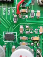
babolcs, Good to hear from you! Finally, someone tries an SRC4392. I like what it does too.
However, shouldn't the switches be set to up, up, dn, dn? If you look closely at the clock on the SRC4392 board it should say the frequency on it. Set the switch for the clock frequency you have. That tells the SRC4392 board microcontroller how to set up the receiver PLL.
Also, if using TOSLINK optical output you should set the upsampler to 96kHz, not 192kHz because optical is unreiiable above 96kHz. Better to use coaxial SPDIF if you want 196kHz out. It may help to know the coaxial SPDIF out on the SRC4392 board is transformer isolated, so no ground loop worries if you use it.
Hi Mark,
I realised just know what you wrote that Toslink is not reliable above 96kHz. so changed to SPDIF, and yes I recognized the small transformer.
Just asking if the I2S bus can be used for connection too? Do I have to connect the 5V too?
Anyway do you have info about the power usage of the SRC4392 board? I just simple power it from an iPhone charge via USB, but the charger is not hot at all, so I suppose not too much. Thx.
Regarding the SRC4392 board, not sure how much current it uses, but it can't be very much. If jumper J1 is removed it can be powered by 5v connected to the pin header terminal so you wouldn't have to use USB power.
Regarding I2S output from the SRC, it could be if the switch for I2S input is turned off then the I2S port works as an output, but I haven't checked. You could try it and see, but if you do then you probably should power the SRC board from the DAC board using the 5v power pin at the DAC I2S header. That way both boards will turn on and off together which is the safest way to avoid damage to the chips from possible over-voltage on the interface pins. (Although it could be the I2S and I2C interface pins are made to be tolerant in that situation, it still seems likely more safe to do it that way. Also, the DAC board 5v regulator should be able to power the SRC board, but it may get a little more warm than usual.)
Regarding I2S output from the SRC, it could be if the switch for I2S input is turned off then the I2S port works as an output, but I haven't checked. You could try it and see, but if you do then you probably should power the SRC board from the DAC board using the 5v power pin at the DAC I2S header. That way both boards will turn on and off together which is the safest way to avoid damage to the chips from possible over-voltage on the interface pins. (Although it could be the I2S and I2C interface pins are made to be tolerant in that situation, it still seems likely more safe to do it that way. Also, the DAC board 5v regulator should be able to power the SRC board, but it may get a little more warm than usual.)
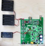
Update on the new ES9038Q2M DAC: Decided to find out if the sound quality problems mostly have to do with the switching power supplies. Tried running IV output stage and AVCC from LiFePO4 batteries. Better, but still not right and not close enough to right either. So... out come the caps and the opamps will be next. Will rebuild IV output to ESS recommendations and try again with batteries. Pics below for viewing enjoyment.
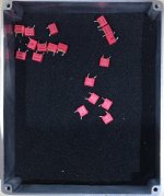
Note: the removed-parts-box is lined with anti-static foam. Keeps parts safe until i figure out what to do with them.
Note: the removed-parts-box is lined with anti-static foam. Keeps parts safe until i figure out what to do with them.
Attachments
Cheap, easy, best allow for many possibilities. Many people here will tell you that you need to do multiple things for best power results. On the board itself the local power supplies could use some fixing. For external power it depends on how much you want to spend and how far you want to go with making the board sound better. The minimum would probably be a +-15v dual rail supply regulated with LM317 and LM337 3-pin regulators. You would need maybe 150mA for the positive rail and maybe not more than 50mA for the negative rail. More current capacity won't hurt of course, but those might serve as reasonable minimums.
If you want a better supply you might consider using a power supply as I mentioned above as a pre-regulator, maybe adjusted up to +-18v, and then use higher performance post-regulators.
Unfortunately, it turns out that DAC chips that can perform at near state of the art sound quality levels require very careful care and feeding. The DAC chip itself is probably the least of the expense and the least problem to achieving very high quality sound. If you feel some skepticism about that you are surely not alone. People often start out skeptical and only find out once they try a few upgrades and fixes what a difference it can make. I'm sure there are other people here who could tell you about their own journeys.
Certainly, achieving measured results ESS claims are possible for the ES9038Q2M chip can be done (-120dB distortion and -122dB noise), but it is not trivial to do.
Last edited:
Well, so many times have I read that with hifi equipment, a good PSU is key, and that's no recent thing, old 1950s literature says the same, that I'm convinced that it is a truism.
After much reading I think I understand about the basics of a PSU:
transformer to step down the AC
then a rectifier to covert it to DC
then a bank of capacitors
then a regulator to smooth out the DC
I'm not clear on the regulator part in terms of what parts to buy, so I'll study that area.
When you say dual rail supply, do you mean a PSU that supplies two independent sets of 15V DC?
How does a dual rail supply differ from a simple PSU like I outlined above? Is it simply duplicating the PSU so you have two identical sets of transformer, rectifier, caps and regulator running in parallel?
- Home
- Source & Line
- Digital Line Level
- ES9038Q2M Board