I did not try ESS recommended opmap circuit. What I did try though is latest version of trident dual shunt from twisteadpearaudio, paul hyness shunt, Salas Ref-D, lt3042. All of them were very good, yet for the image stability, clear background LifePo4 is the winner. It is like everything became, clear, calm and relaxing. It reminds me my pcm1704 dac that I used to build some time ago.
This is what we found many years ago. On most applications straight
batteries were superior to any form of regulation. At that time regs like 3042
were not quite out and I thought that these might surpass batteries
performance.
I'll be interested to see how super (ultra) caps go. Also worth a try is
inserting a low ohmic value (say 4.7R) series resistor after a VHQ reg (3045)
feeding the super cap. The theory here is whatever sonic influence the reg
has, it is attenuated by 40dB or so, depending on Z / size of cap.
Also I'm not sure of the HF performance of supercaps. Have to look into this.
T
Yep shortening the leads should help. I will try it.
The output stage is discrete class A zero global feedback Legato 3.1 from twistedpearaudio (my favorite one).
Also have always had best results from ZFB I-V stages but they have to be
designed with very low distortion which is a huge challenge for DACs like
ES9038 that have low OP Z and high current swing.
With DAC's like 1794 which are much closer to true CCS OP (very high Z) it's
a lot easier.
With opamp AVCC PSU only and DAC in voltage mode with orig. clock it was somehow more relaxing but dynamic was not as good as it is in current mode now.
Could there be any problems with the +-15v power quality? Also, do you have any cordless phones in the vicinity? Sometimes things can seem to get worse on the way to getting better because you have exposed some distortion that was always there but was obscured by even bigger distortion. Could also be you are ready for upsampling. My current recommendation is for AK4137 which can make a big difference. Still have a spare SRC4392 I am willing to send to somebody who has done enough mods to be ready for trying it. I could send it to Europe I guess since nobody close by has indicated they are ready for that step. If you were to try it and find it helps according to your ears then I would encourage you to try to find some way to go for the AK4137 with high speed PCM/I2S and DSD capabilities.
Hello Mark,
I use this PSU. I have a similar one in my active XO and it works quite well - not to hide the issue I had to replace the TL431 reg. after removing the power transistors to place them under the board with direct connection to the aluminum case for better cooling. After that the left side TL431 only gave 3V instead of 15 on one channel...
I placed everything into the case and yes, I have a Dect phone in 4m distance, but the phone is on base station for charging most of the time.
Regarding SRC thanks a lot for your offer to ship to EUROPE! - I am using RASPI with room correction SW with upsampling to 96kHz and IIS output to DAC. I don´t want to make the system more complex from HW side.
Regarding controler chip hacking - thanks a lot for your support. First I will check what the Schmitt Trigger for my clock will do and I still have some feeling the caps for AVCC could change bass Performance into the one or other direction. Did you test different types here? Why does nobody talk about big ceramic or film caps instead of the 47uF elko at this place?
Ah, ha! DECT phone base stations are always broadcasting every 10ms! They produce a lot of RF that LME49720 opamps pick up and rectify. Either the base station needs to be powered off or the DAC should be in a good, well shielded case if within several feet of a DECT base station. I don't know how far away it has to be but I can see FFT spurs that go away if the base station is unplugged, and it is at least 10 feet away from the DAC here.
Regarding AVCC and caps, the caps shouldn't change the sound of the ESS opamp AVCC circuit if it is working properly. They used from 10uf to 47uf, but no indication they say improvement with more than that. If there is a problem with bass it should show up as some kind of distortion, linear or nonlinear. AVCC modulation probably has to be at least in part mutiplicative which would mean that AVCC modulation would be expected to cause IMD with the audio signal. Therefore, I tend to be concerned that people who play around with caps rather that use a very-close-to-the-DAC, well-implemented opamp regulator probably have other problems they are not aware of.
Regarding upsampling to 96kHz, that is a good start. Maybe. Upsamplers very a lot in quality and distortion they produce. The best produce distortion down at -140dB to maybe -160dB. Most software upsamplers are not at that level of quality and thier side-effects are audible. Still, what you have there might let you try the minimum-phase, slow-transition reconstruction filter and try to reduce group delay and see how it sounds. However, some group delay can be introduced by the upsampler so you have to be careful that you are making things better rather that worse. The best I have heard so far with these DACs is the AK4137, as I have been mentioning here and there.
Last edited:
Ah, ha! DECT phone base stations are always broadcasting every 10ms! They produce a lot of RF that LME49720 opamps pick up and rectify. Either the base station needs to be powered off or the DAC should be in a good, well shielded case if within several feet of a DECT base station. I don't know how far away it has to be but I can see FFT spurs that go away if the base station is unplugged, and it is at least 10 feet away from the DAC here.
Regarding AVCC and caps, the caps shouldn't change the sound of the ESS opamp AVCC circuit if it is working properly. They used from 10uf to 47uf, but no indication they say improvement with more than that. If there is a problem with bass it should show up as some kind of distortion, linear or nonlinear. AVCC modulation probably has to be at least in part mutiplicative which would mean that AVCC modulation would be expected to cause IMD with the audio signal. Therefore, I tend to be concerned that people who play around with caps rather that use a very-close-to-the-DAC, well-implemented opamp regulator probably have other problems they are not aware of.
Regarding upsampling to 96kHz, that is a good start. Maybe. Upsamplers very a lot in quality and distortion they produce. The best produce distortion down at -140dB to maybe -160dB. Most software upsamplers are not at that level of quality and thier side-effects are audible. Still, what you have there might let you try the minimum-phase, slow-transition reconstruction filter and try to reduce group delay and see how it sounds. However, some group delay can be introduced by the upsampler so you have to be careful that you are making things better rather that worse. The best I have heard so far with these DACs is the AK4137, as I have been mentioning here and there.
Good News i received the src4392. And also some components from mouser. So on avcc I can replace the several small caps to Elna silmic II 470uF. And added the up sampler. Like the change in Sound
")
Attachments
babolcs, Good to hear from you! Finally, someone tries an SRC4392. I like what it does too.
However, shouldn't the switches be set to up, up, dn, dn? If you look closely at the clock on the SRC4392 board it should say the frequency on it. Set the switch for the clock frequency you have. That tells the SRC4392 board microcontroller how to set up the receiver PLL.
Also, if using TOSLINK optical output you should set the upsampler to 96kHz, not 192kHz because optical is unreiiable above 96kHz. Better to use coaxial SPDIF if you want 196kHz out. It may help to know the coaxial SPDIF out on the SRC4392 board is transformer isolated, so no ground loop worries if you use it.
Last edited:
babolcs, Good to hear from you! Finally, someone tries an SRC4392. I like what it does too.
However, shouldn't the switches be set to up, up, dn, dn? If you look closely at the clock on the SRC4392 board it should say the frequency on it. Set the switch for the clock frequency you have. That tells the SRC4392 board microcontroller how to set up the receiver PLL.
I use CD therefor I used the 44,1 related freq series for output too. And it can be achieved with SW4 on. SW1,SW2 for 176,4khz and sw3 off for the spdif input. Am I wrong?
I use CD therefor I used the 44,1 related freq series for output too. And it can be achieved with SW4 on. SW1,SW2 for 176,4khz and sw3 off for the spdif input. Am I wrong?
Yes, I think that's wrong.
The switch-4 should be set to whatever clock is soldered onto the SRC4392 board. If you look with a magnifying glass you can read the number on the clock then set the switch-4 to the correct setting to match the clock you have.
The SRC4392 will automatically adjust to the input frequency you send. It will detect that the input stream is 44.1kHz, so you don't have to do anything for that.
The output sample rate switches are for all output and any input. The output sample rate is independent of the input sample rate. The reason is that the SRC4392 chip can be programmed in to work in different ways. On this board it is programmed to output a constant sample rate set by switch-1 and switch-2. Any input sample rate will be automatically detected and converted to the output sample rate you have selected.
I will attach a .pdf below that may help clarify the settings.
Attachments
Mark, I don´t think it is the DECT phone. It has an automatic signal power controle by distance from base station (which is zero in my case). Further the DAC is in a completely closed aluminum case now (opamps additionaly shielded with aluminum cooling devices) and I used other opamp implementations with 49720 that did not run as hot in same room so I guess this RF come from DAC chip or is introduced into power rails from DAC board - but easy to try it, switching the phone off ;-)
I know that SW upsampler variate in quality. But this is implemented by the SW I use on my PI combined with room correction convolution. All files are upsampled to 96kHz before convolution. An upgrade might be to make the convolution and upsampling on the server side (e.g. by roon..) by a PC with more calculation power and stream upsampled files to the RASPI... Also upsampling from 44.1kHz to 96kHz is not ideal - probably better to 88,2kHz or 176,4kHz..
I know that SW upsampler variate in quality. But this is implemented by the SW I use on my PI combined with room correction convolution. All files are upsampled to 96kHz before convolution. An upgrade might be to make the convolution and upsampling on the server side (e.g. by roon..) by a PC with more calculation power and stream upsampled files to the RASPI... Also upsampling from 44.1kHz to 96kHz is not ideal - probably better to 88,2kHz or 176,4kHz..
The upsampler in Reaper DAW is pretty good if set to 'Extreme High Quality, and with dither enabled. It is around -140dB distortion, but even at that there is some audible group delay sound. And of course, that SRC quality on a general purpose CPU is slow and can't be done in real time. It takes dedicated DSP hardware for real-time SRC performance at that level. No upsampler of any kind I have heard can match AK4137 at maximum sample rate.
To see what type of phone you have just good it or read the manual. It should say. Most are DECT. You could try powering it off and seeing if you can hear any change in sound. If not, I guess it isn't a problem. At least it isn't with the remaining distortion you still have. It could become a limiting factor later. Might want to check again then.
To see what type of phone you have just good it or read the manual. It should say. Most are DECT. You could try powering it off and seeing if you can hear any change in sound. If not, I guess it isn't a problem. At least it isn't with the remaining distortion you still have. It could become a limiting factor later. Might want to check again then.
Last edited:
Don't know. It is a known issue especially with those particular opamps. You should be able to see spurs on an FFT if there is a problem, and if you have a sound card you can use for that. Thing about grounding tin foil at a few GHz is that the ground wire is a big inductor. Maybe a wide copper strap to the ground plane would be closer to working. Only way to know for sure it try it and see. Even then, turning the chassis a little one way or another could change things. Best is a stout steel case, such as what Benchmark uses. I am doing my experiments now inside a steel file server case. I can put the lid on and I have it pretty closed off. Still have to see if wires going in and out are acting like coupling antennas. You know, like they use to make car radios work in tunnels. Set up an antenna outside the tunnel then connect that to a wire that runs through the tunnel hanging from the top. The outside antenna picks up radio waves and the wire in the tunnel re-broadcasts them. We don't want that effect inside our DAC case.
Last edited:
Interesting news. The new ES9038Q2M Chinese DAC arrived today. The fancy new version with bluetooth and IV outputs, all that stuff. GAO su5 ES9038Q2M DAC Supports input Bluetooth 5.0 APT X USB XMOS 208 fiber coaxial highest audio decoding 32 bit/384kHz DSD256 -in Digital-to-Analog Converter from Consumer Electronics on Aliexpress.com | Alibaba Group
It has a built-in headphone amp, XMOS USB board with what looks to be a couple of different sized USB connectors on the back. Just got done trying it out.
It is distorted. What did I expect, right? It runs off a 12v, 2A. wall wart. Looks like it has IV to differential outputs. The headphone output sounds excessively bass-heavy and distorted. Tried the line outputs into my LME49600 HPA, and it sounded bass-light and distorted. The distortion may be a little less than the DAC boards we have been modding so far, but not a whole lot less so.
On the front panel there is a power button and rotary encoder knob that controls volume. Pushing in on the knob actives a switch that selects the desired input, USB, BT, TOSLINK, or SPDIF. That's it. Doesn't seem to be any way to change any other settings. There is a little hole in the front panel that looks like poke-hole, but pressing on what looks like it might be a switch inside doesn't seem to do anything. Maybe there is some trick to it, but so far I haven't figured out what might be.
Looks like the DAC is going to need some work. +-12v or +-15v power I'm guessing as the possible first thing. Haven't measured any voltages inside it yet, though. Will try to get some closeup pics soon so anyone interested can have a look.
Last edited:
About that RF on LME49720s. What about if we put a copper foil on top of the body of the IC and then ground the foil. Tin Hats so to speak? I have copper foil sheets with adhesive that I can peel and stick.
You can buy the HA version with metal package. Price is 4 times more.
Yes, I think that's wrong.
The switch-4 should be set to whatever clock is soldered onto the SRC4392 board. If you look with a magnifying glass you can read the number on the clock then set the switch-4 to the correct setting to match the clock you have.
The SRC4392 will automatically adjust to the input frequency you send. It will detect that the input stream is 44.1kHz, so you don't have to do anything for that.
The output sample rate switches are for all output and any input. The output sample rate is independent of the input sample rate. The reason is that the SRC4392 chip can be programmed in to work in different ways. On this board it is programmed to output a constant sample rate set by switch-1 and switch-2. Any input sample rate will be automatically detected and converted to the output sample rate you have selected.
I will attach a .pdf below that may help clarify the settings.
Ok. Got it changed sw4 to off.
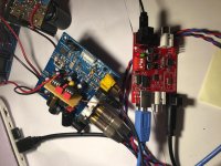
Hi Freezebox, All
I have done the I/V stage. Although not 100% copy of your circuit. Since I'm lazy I used the LP filter stage which was on the panel, and added the I/V stage according you schematics. Thanks it works fine.
In the I/V stage I used the LME49720. and since I didn't have at home more I used in the LP filter stage OPA2134 - will be change to LME49720 too.
(some advices can be found here also: https://www.by-rutgers.nl/IV-converter.html)
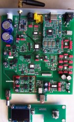
So the current status summary of all MODs I've done:
1) I/V stage
as described above
2) AVCC_L,R
I powered them with an OPA based solution. Described here OPA based Ultra Low noise VREF for DAC more detailed in post 70.
3) Power supplies
- All the panel's power supply is separated with LP5907 and this is powered with a LM317+TL431 modul
- the controller remained on the 7805 (separated)
This 2 were described in this thread in the post 1306
- The I/V stage with the LP filter and the AVCC OPA based REF are powered from a SALAS shunts v1.3
4) CAPs
- I changed the important power CAPs to Nichicon MUSE types.
5) Upsample
- I ordered the upconversion unit, suggested by Mark based on the SRC4392
(this not yet arrived yet)
I do not intend to replace the clock - according some posts here it can further enhance the voice, but maybe not too much comparing with the above described MODs.
So thanks again for your inspirations and helps. Since I'm satisfied with the voice I really stop here the moddings on this panel. I will try to find a box and will put my ugly panel into it.
See some more pictures. Not nice, but sounds OK.
babolcs
Just to have the complete picture in the post above I summarized all the moddings. Currently with the extension that src4392 arrived and all the OPAs have been changed to 49720. And on the output of OPA based 00reg the caps are changed to elna silmic II 470uF
Yes more clarity softer sound then nichicon and wider stage. As it is written at several places.
On the famous pawnshop Jazz cd and the deedee bridgewater (live at Yoshi’s) cd so much more details appeared with this last steps. ...
So on my side only a box is needed. (Expectedly not too much effect on sound.
). (Anyway my OPA based reg’s bass is really strong and clear character)Thanks again for the team work.
Last edited:
Ps: Mark just for you
I will build the lme49600 based headphone amp
Thank you. Just to be aware they are fast and can oscillate easily if care is not taken to use a ground plane and proper decoupling. Just a word to the wise. Somewhere I wrote some things about what I found out when modding my HPA. Think it may have been back here: http://www.diyaudio.com/forums/digital-line-level/314935-es9038q2m-board-63.html#post5402398
Also, it started as one of these, but I found I had to do some work on it: 1PCS LME49720NA+LME49600 headphone amplifier KIT | eBay
If you would like to talk about it some, be happy to.
Thought I would follow up with a pic of the boards inside the new DAC. I have labeled some of the parts, but probably have to zoom in all the way to read the tiny writing. Still haven't traced out AVCC, but already no wonder it sounds distorted. Besides the switching power supplies the IV opamps are TL072. Don't know what these guys were thinking since those opamps distort more in to low impedance loads and the IV feedback resistor is more than low enough.
EDIT: Looks like diyaudio has messed up my good quality jpeg by compressing it too much. If it is too illegible let me know I will try to find a way to put up something better. Maybe cut it into pieces.
EDIT: Looks like diyaudio has messed up my good quality jpeg by compressing it too much. If it is too illegible let me know I will try to find a way to put up something better. Maybe cut it into pieces.
Attachments
Last edited:
- Home
- Source & Line
- Digital Line Level
- ES9038Q2M Board