Hello !
OpenUAC2 project implementation on custom HW with ES9038 is on the way")

The STM32 USB->I2S work, I2S signals looks good but es9038 didn't generate any signal.
I can read and write through I2C on es9038, I was surprised as the i2c address of es9038 is not 0x90/0x92 like mentioned on datasheet but 0x48 ? There is also another strange thing as the res1 register default value is not b11001100 but b10001100 ?
Clock on es9038 is good, voltage rails on es9038 looks good, I certainly miss something on es9038 init. If someone know how to simply output a analog signal with I2S data ?
OpenUAC2 project implementation on custom HW with ES9038 is on the way
The STM32 USB->I2S work, I2S signals looks good but es9038 didn't generate any signal.
I can read and write through I2C on es9038, I was surprised as the i2c address of es9038 is not 0x90/0x92 like mentioned on datasheet but 0x48 ? There is also another strange thing as the res1 register default value is not b11001100 but b10001100 ?
Clock on es9038 is good, voltage rails on es9038 looks good, I certainly miss something on es9038 init. If someone know how to simply output a analog signal with I2S data ?
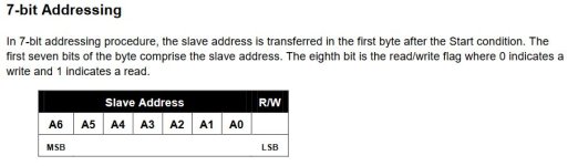
These devices use 7-bit addressing (see attachment). For some reason ESS gives the address in 8-bit format in the datasheet (i.e. 0x48 << 1)I was surprised as the i2c address of es9038 is not 0x90/0x92 like mentioned on datasheet but 0x48
Can you list what values you use to initialize the registers?
Attachments
Oups a newbie misunderstanding!
I tried several combinaisons of registers, last try I only made a reset cycle toggling reset pin these way: L wait 10ms H.

I think it's maybe my volume control in fault :

I have binary stream on I2S bus, I see I2S_WS frequency change accordingly with Fs (ie 48ks i2s_ws=48khz, 96ks 96khz)
I comment all other functions
Success not so far
I tried several combinaisons of registers, last try I only made a reset cycle toggling reset pin these way: L wait 10ms H.
I think it's maybe my volume control in fault :
I have binary stream on I2S bus, I see I2S_WS frequency change accordingly with Fs (ie 48ks i2s_ws=48khz, 96ks 96khz)
I comment all other functions
Success not so far
That does not look right. You seem to use volume value as register id. And you really should get rid of "AK4490" stuff in code as well as namings.I think it's maybe my volume control in fault
I check if I have 1.2V on pin 15: ok
check pin 21 reset: high level ok
I test with a volume value of 0x0 no change

You totally right I have to get rid of all reference to ak4490r and rewrite these portion of code, I'm only doing a quick check to be sure dac is working.
Next step: will try to probe signals directly on dac qfn package but maybe not tonight, a short circuit is quickly happening at the end of a day
check pin 21 reset: high level ok
I test with a volume value of 0x0 no change
You totally right I have to get rid of all reference to ak4490r and rewrite these portion of code, I'm only doing a quick check to be sure dac is working.
Next step: will try to probe signals directly on dac qfn package but maybe not tonight, a short circuit is quickly happening at the end of a day
Your "ak4490" stuff confused me so my previous post was not correct about your volume control. But even without any volume control you should have the default -40dB output.
Are you are able to read sensible values from registers?
What are the I2S signal frequencies (MCK, BCK, LRCK)?
Are you are able to read sensible values from registers?
What are the I2S signal frequencies (MCK, BCK, LRCK)?
Yep, can read, write and read back registers.

DAC_DATA looks good streaming audio data
DAC_LRCLK is 96Khz
DAC_BCLK is around 6.144 Mhz
DAC_MCLK is 49.152Mhz (feed by stm32)
I measure those signals probing on a resistor network array, maybe solder between pads and es9038 are not good. I think about testing spdif input. Also output the lock bit /register 64 could be helpful for me, I can map on a led to see.
If it helps, attached is logic analyzer hex dump of the boot code for a Chinese ES9038Q2M dac. As can be seen there is a lot of looping and checking of status bits. Eventually on the last page, the code enables the dac audio output (in register 14, IIRC).
Attachments
Hello
Finally, it works it just work few second ago, so I have to properly understand how and why but... great!!!!
I had one issue, I used the i2c write meme function with IT this doens't works for me, I replace it with no IT it works bit7 set of reg14.
I modify these things:

and my init sequence:

I see on scope the wave is not stable, there is some issue to fix, but hw seems to be good and that was my goal for this week
Here the sinus of victory

Guys of you go skiing in my country (Grenoble/French Alps) I have some beers to share with you!
Finally, it works
it just work few second ago, so I have to properly understand how and why but... great!!!!I had one issue, I used the i2c write meme function with IT this doens't works for me, I replace it with no IT it works
bit7 set of reg14.I modify these things:
and my init sequence:
I see on scope the wave is not stable, there is some issue to fix, but hw seems to be good and that was my goal for this week
Here the sinus of victory
Guys of you go skiing in my country (Grenoble/French Alps) I have some beers to share with you
!Unstable in what way? Are you using Normal trigger mode or Auto trigger mode? Sometimes Normal mode will give a more stable display.I see on scope the wave is not stable, there is some issue to fix,...
Unstable the way the signal generated by dac goes on/off/on/off not accurately measured that. I was on auto trigger. I have to spy i2c bus and RESETB bin to see what appends.
Also signal is noisy and very low in amplitude; I get max of +/-200mV (when I set reg15 volume register to 0x0, if I set more than 0x0 amplitude decrease accordingly this looks normal). I doubt I understand well the output stage of this dac, in first understanding I think it was a current output dac and then implement this schematic:

Opamps are powered with dual supply +5V and -5V and I need a single ended signal of max +/-1.5V peak amplitude, after I made a single ended to diff conversion as I need a diff signal for my power amp. Values of 400R for i/s stage is based upon typical current output dac of +/-3.9mA centered on a -6.2mA dc current, ex : https://mi-take.biz/system72/DAC2020/ES9038Q2M/ES9038Q2M_DAC.html
Also signal is noisy and very low in amplitude; I get max of +/-200mV (when I set reg15 volume register to 0x0, if I set more than 0x0 amplitude decrease accordingly this looks normal). I doubt I understand well the output stage of this dac, in first understanding I think it was a current output dac and then implement this schematic:
Opamps are powered with dual supply +5V and -5V and I need a single ended signal of max +/-1.5V peak amplitude, after I made a single ended to diff conversion as I need a diff signal for my power amp. Values of 400R for i/s stage is based upon typical current output dac of +/-3.9mA centered on a -6.2mA dc current, ex : https://mi-take.biz/system72/DAC2020/ES9038Q2M/ES9038Q2M_DAC.html
I2C bus is open collector. Sometimes there may be weak pullup resistors in a device but for high speed operation external pullups are required. Maybe 4.7k or even 2.2k. Depends.
Regarding output stages for ESS dacs, there is very high RF content coming out of the dac analog outputs. Some of it may be too fast for the I/V opamp so it can go around the opamp through the integrator cap. The RF is also hard on the differential summing MFB filter stage. You get sound, but SQ may not be very good if there are problems.
Regarding output stages for ESS dacs, there is very high RF content coming out of the dac analog outputs. Some of it may be too fast for the I/V opamp so it can go around the opamp through the integrator cap. The RF is also hard on the differential summing MFB filter stage. You get sound, but SQ may not be very good if there are problems.
Guess I would add that +-5v for the opamps isn't very much. Closer to +-15v is where they may work better. Topping used +-12v for D90, but it was with an AKM chip.
There can be benefit to more passive filtering between the I/V opamp outputs and the balanced MFB filter stage.
Also, dacs always need two critical analog references. The critical voltage reference is at AVCC. The critical analog time reference is the master clock (MCLK), at least for this dac chip.
Any noise on the analog references becomes convolved in the frequency domain with the analog audio outputs of the dac. For small errors, an small time error is about as bad a small Vref (AVCC) error, although they are not exactly the same.
BTW, welcome to the arcane world of dacs
link to Japanese designer with analog power supply
http://triesteaudio.blog.fc2.com/blog-entry-263.html?sp
http://triesteaudio.blog.fc2.com/blog-entry-248.html?sp
http://triesteaudio.blog.fc2.com/blog-entry-263.html?sp
http://triesteaudio.blog.fc2.com/blog-entry-248.html?sp
Hi,
I didn't make good measures, maybe my scope probe .... so some good news and good measures now
The OpenUAC2 project works just like a charme, no instabillities (bad probe I guess) and volume function works perfectly for me with this:

Off course I ask es9038 to link both channels with this init:

Now electronic side, I use a 400R resistor as part of I/V converter, this resistor generate only about +/-500mV around AVCC/2 (1.65V), so I guess the current value I use for sim was not good for es9038, I replace 400r resistor with a 1kR, yes, now get +/-2V around 1.65V... good!
I aslo made a basic mistake with my SE to DIFF stage with opa1632 then I fix it (double the gain).
Then now can plug my qa403 at the output of my se->diff converter, results are not 'foolish' but encouraging!
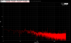
I try several combination of MCLK frequency (24.576, 49.152, 98.304) and several Fs rate, results are identical, this mean than my implementation is noisi.
First noise floor on a 98.304 stm32 clk try (same results with 24 or 49m):

I add left chan as reference 50R bnc terminators.
And THD with 49.152m and 384ks Fs:

I put this screen to show that 384Fs with 49M clock is not a good idea.
Let's give a try with a 98.304Mhz clock:

Far better!
Other Fs/MCLK combinations show similar results than the one just above.
Indeed I use a poor man power supply sheme. My main input is a 24DC power supply, then a dc/dc converter generate a 5.5V, then a LM27762 generate +5/-5V rails for opamps, then 3*low noise LP5907 generate AVCC_R, AVCC_L and VCCA for es9038 feeded by lm27762 +5V output.
So, I'm good enough for my power amp (wich own a noise level about -94dBV), but will try the MCLK optimisation: use a low noise XO (NZ5220SDA) instead of stm32 MCO output For voltage noise I think I can't have a big optimisation tricks
Fun playing with dac, this is my second attemps, first was using a Xmos and PCM1792.
I didn't make good measures, maybe my scope probe .... so some good news and good measures now
The OpenUAC2 project works just like a charme, no instabillities (bad probe I guess) and volume function works perfectly for me with this:
Off course I ask es9038 to link both channels with this init:
Now electronic side, I use a 400R resistor as part of I/V converter, this resistor generate only about +/-500mV around AVCC/2 (1.65V), so I guess the current value I use for sim was not good for es9038, I replace 400r resistor with a 1kR, yes, now get +/-2V around 1.65V... good!
I aslo made a basic mistake with my SE to DIFF stage with opa1632 then I fix it (double the gain).
Then now can plug my qa403 at the output of my se->diff converter, results are not 'foolish' but encouraging!
I try several combination of MCLK frequency (24.576, 49.152, 98.304) and several Fs rate, results are identical, this mean than my implementation is noisi.
First noise floor on a 98.304 stm32 clk try (same results with 24 or 49m):
I add left chan as reference 50R bnc terminators.
And THD with 49.152m and 384ks Fs:
I put this screen to show that 384Fs with 49M clock is not a good idea.
Let's give a try with a 98.304Mhz clock:
Far better!
Other Fs/MCLK combinations show similar results than the one just above.
Indeed I use a poor man power supply sheme. My main input is a 24DC power supply, then a dc/dc converter generate a 5.5V, then a LM27762 generate +5/-5V rails for opamps, then 3*low noise LP5907 generate AVCC_R, AVCC_L and VCCA for es9038 feeded by lm27762 +5V output.
So, I'm good enough for my power amp (wich own a noise level about -94dBV), but will try the MCLK optimisation: use a low noise XO (NZ5220SDA) instead of stm32 MCO output
For voltage noise I think I can't have a big optimisation tricks Fun playing with dac, this is my second attemps, first was using a Xmos and PCM1792.
Attachments
- Home
- Source & Line
- Digital Line Level
- ES9038Q2M Board