Hello !
OpenUAC2 project implementation on custom HW with ES9038 is on the way")

The STM32 USB->I2S work, I2S signals looks good but es9038 didn't generate any signal.
I can read and write through I2C on es9038, I was surprised as the i2c address of es9038 is not 0x90/0x92 like mentioned on datasheet but 0x48 ? There is also another strange thing as the res1 register default value is not b11001100 but b10001100 ?
Clock on es9038 is good, voltage rails on es9038 looks good, I certainly miss something on es9038 init. If someone know how to simply output a analog signal with I2S data ?
OpenUAC2 project implementation on custom HW with ES9038 is on the way
The STM32 USB->I2S work, I2S signals looks good but es9038 didn't generate any signal.
I can read and write through I2C on es9038, I was surprised as the i2c address of es9038 is not 0x90/0x92 like mentioned on datasheet but 0x48 ? There is also another strange thing as the res1 register default value is not b11001100 but b10001100 ?
Clock on es9038 is good, voltage rails on es9038 looks good, I certainly miss something on es9038 init. If someone know how to simply output a analog signal with I2S data ?
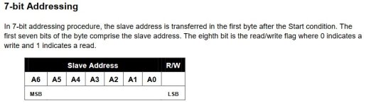
These devices use 7-bit addressing (see attachment). For some reason ESS gives the address in 8-bit format in the datasheet (i.e. 0x48 << 1)I was surprised as the i2c address of es9038 is not 0x90/0x92 like mentioned on datasheet but 0x48
Can you list what values you use to initialize the registers?
Attachments
Oups a newbie misunderstanding!
I tried several combinaisons of registers, last try I only made a reset cycle toggling reset pin these way: L wait 10ms H.

I think it's maybe my volume control in fault :

I have binary stream on I2S bus, I see I2S_WS frequency change accordingly with Fs (ie 48ks i2s_ws=48khz, 96ks 96khz)
I comment all other functions
Success not so far
I tried several combinaisons of registers, last try I only made a reset cycle toggling reset pin these way: L wait 10ms H.
I think it's maybe my volume control in fault :
I have binary stream on I2S bus, I see I2S_WS frequency change accordingly with Fs (ie 48ks i2s_ws=48khz, 96ks 96khz)
I comment all other functions
Success not so far
That does not look right. You seem to use volume value as register id. And you really should get rid of "AK4490" stuff in code as well as namings.I think it's maybe my volume control in fault
I check if I have 1.2V on pin 15: ok
check pin 21 reset: high level ok
I test with a volume value of 0x0 no change

You totally right I have to get rid of all reference to ak4490r and rewrite these portion of code, I'm only doing a quick check to be sure dac is working.
Next step: will try to probe signals directly on dac qfn package but maybe not tonight, a short circuit is quickly happening at the end of a day
check pin 21 reset: high level ok
I test with a volume value of 0x0 no change
You totally right I have to get rid of all reference to ak4490r and rewrite these portion of code, I'm only doing a quick check to be sure dac is working.
Next step: will try to probe signals directly on dac qfn package but maybe not tonight, a short circuit is quickly happening at the end of a day
Your "ak4490" stuff confused me so my previous post was not correct about your volume control. But even without any volume control you should have the default -40dB output.
Are you are able to read sensible values from registers?
What are the I2S signal frequencies (MCK, BCK, LRCK)?
Are you are able to read sensible values from registers?
What are the I2S signal frequencies (MCK, BCK, LRCK)?
Yep, can read, write and read back registers.

DAC_DATA looks good streaming audio data
DAC_LRCLK is 96Khz
DAC_BCLK is around 6.144 Mhz
DAC_MCLK is 49.152Mhz (feed by stm32)
I measure those signals probing on a resistor network array, maybe solder between pads and es9038 are not good. I think about testing spdif input. Also output the lock bit /register 64 could be helpful for me, I can map on a led to see.
If it helps, attached is logic analyzer hex dump of the boot code for a Chinese ES9038Q2M dac. As can be seen there is a lot of looping and checking of status bits. Eventually on the last page, the code enables the dac audio output (in register 14, IIRC).
Attachments
- Home
- Source & Line
- Digital Line Level
- ES9038Q2M Board