I have been looking at the specs on the LT3042 and LT3045 again. The load step transient response appears to show something significant. If I am reading it correct we are looking at 20mV (millivolts) coming from a step load. that is 20millivolts. (We need 1 microvolt to achieve -120db according to Ted Smith for DSD.) The LT3042 might be good for steady loads but it might be not as good for providing a reference voltage load in heavy load situations....i.e. transients at low frequencies. Can someone comment as I am not experienced at this.
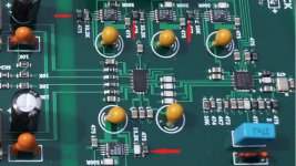
Yesterday a new bord arived,with 4x LT3042. The arrows show the bypasse condensator.
@democles, Just looked at the pic you posted. Looks like the LT3042 regulators have 4.7uf caps for Cset. Don't know if you have been following the thread here, but if so you might consider increasing those to 22uf and see if you notice any difference in SQ.
Also, it would be interesting if you could post some more close-up pics of the new board. It we could see how far the clock is from the DAC chip and what some of the part numbers are on the other ICs it would be great.
Last edited:
The load step transient response appears to show something significant.
That is for a 490mA current step, from 10mA to 500mA then back to 10mA. The LME49720 opamps can only put out 23mA maximum. Therefore, the graph is showing a load change much more severe than would be expected to occur if powering AVCC.
Seems like we still don't know enough to say how well LT3045 might work with the maximum recommended Cset of 22uf. Somebody will have to do some work to find out, otherwise the safe thing to do would probably be to go with the ESS recommended circuit.
Last edited:
I have been looking at the specs on the LT3042 and LT3045 again. The load step transient response appears to show something significant. If I am reading it correct we are looking at 20mV (millivolts) coming from a step load. that is 20millivolts. (We need 1 microvolt to achieve -120db according to Ted Smith for DSD.) The LT3042 might be good for steady loads but it might be not as good for providing a reference voltage load in heavy load situations....i.e. transients at low frequencies. Can someone comment as I am not experienced at this.
I am not experienced either, but I believe this is a pretty relevant issue. certainly, a stable AVCC is a key for SQ, but that depends on DACs power demands upon different modes, what are rather obscure. i am not sure whether the datasheet even deals with these matters, so perhaps on board measurements may help.
personally I am convinced that discrete regs are the way to go, because they offer much more freedom to adjust. OK, they will turn out relatively bulk, but that is hardly an issue.
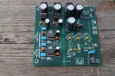
Here we go.
Thanks. That helps some, but maybe a few more questions?
The only clock I see appears to go into a chip on the right? I can't read the part number on the clock or on the chip next to it.
Also, it would be nice to know the part number of the chip in the upper right hand corner of the pic next to where the MCLK jumper is.
One of the chips is there must be a microcontroller to program the DAC chip, I would think. Not sure what the other chip would be.
In addition, I am wondering about the part numbers on the power supply rectifiers, looks like maybe a bridge module in there? Hopefully, fast turn-off soft-recovery types.
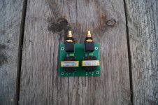
And this.
Right. It is a differential output board only. No single-ended outputs. The transformers provide the single-ended conversion, and maybe a little special 'iron' sound.
i am not sure whether the datasheet even deals with these matters, so perhaps on board measurements may help.
I think it is pretty much up to the designer to measure some things for their particular application. There are many different ways to operate the device.
This is from the seller of the board.
After SPDIF coaxial digital signal is input by Murata Isolation Transformer, it is demodulated by SA8804. SA8804 is the best SPDIF demodulator chip in the world. The internal PLL regenerates MCLK signal jitter which is less than one-third of the average receiver. After optimizing the design to play a higher level. The SA8804 outputs I2S signals, including the MCLK signal required by the ES9038Q2M. This allows us to turn off the ASRC circuitry inside the ES9038Q2M, enabling the Q2M chip to operate in synchronous clock mode.
After SPDIF coaxial digital signal is input by Murata Isolation Transformer, it is demodulated by SA8804. SA8804 is the best SPDIF demodulator chip in the world. The internal PLL regenerates MCLK signal jitter which is less than one-third of the average receiver. After optimizing the design to play a higher level. The SA8804 outputs I2S signals, including the MCLK signal required by the ES9038Q2M. This allows us to turn off the ASRC circuitry inside the ES9038Q2M, enabling the Q2M chip to operate in synchronous clock mode.
I guess LT3042/45 chips are more than fit to provide clean Vref for i/v stage. additional post filtering can be done if necessary. sure, ESS docs available emphasizes clean Vref very much, but again regarding AVCC requirements, it is a little unclear. the regulator has to work in front of a load which will draw some current at some frequency. what here is the most important factor? the usual low impedance over wide frequency range?... The LME49720 opamps can only put out 23mA maximum. ...
additional post filtering can be done if necessary.
Not really, according to the LT3045 data sheet. They say adding more than 10uf output capacitance doesn't help due to it causing a reduction in regulation bandwidth.
Also, if a resistor was added to the output to make more of a filter that might be bad from the perspective of raising AVCC power supply output impedance. ESS could have done something like that with their recommended circuit and they did not, perhaps because it would have made regulation/noise worse.
So far as we know at this point the best that could be done with an LT3045 for this application would be to try increasing Cset to 22uf. Then that could be compared with the ESS circuit using DAC output distortion measurements and listening tests. Maybe we will find out more later, but that seems to be about it for now.
Last edited:
Yesterday a new bord arived,with 4x LT3042. The arrows show the bypasse condensator.
Where did you get the board? I think the seller posts here but he doesn't provide links.
Edit: never mind. Found it.
Last edited:
This is from the seller of the board.
After SPDIF coaxial digital signal is input by Murata Isolation Transformer, it is demodulated by SA8804. SA8804 is the best SPDIF demodulator chip in the world. .
Hmm, I know about the WM8804, but I can't find any info on a Savitech SA8804.
Regarding SA8804, MCLK, and jitter, the best DACs that I know of in any detail use ASRC and ultra-low jitter clocking. I am not aware of any evidence that SA8804 can produce lower jitter than other alternatives, or that turning off ASRC is necessarily of any help for SQ, at least with the newest ESS chips including 9028 and 9038 families. With the older 9018 ASRC quality wasn't as good, but ASRC can be done at much lower distortion levels than the DAC is capable of reproducing. For example SRC4392 is rated for -140dB THD, and AK4137 as low as -150dB THD. The ESS DACs are only capable of -120dB or -122dB distortion numbers, so ASRC should not be an issue. In fact, Benchmark DAC-3 uses ASRC and so does Crane Song Solaris. So, one has to wonder what the designer of the board you have was thinking, although it may very well be a much better board than the boards we started out with in this thread.
Last edited:
Where did you get the board? I think the seller posts here but he doesn't provide links.
Edit: never mind. Found it.
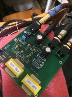
I had to wait a long time to arrive.
The factory chainses so quick to other boards,this one might not be avalibel.
Wait til i tested it.
This is the last one with discreet I/V output.
Attachments
I think it is pretty much up to the designer to measure some things for their particular application. There are many different ways to operate the device.
certainly. to get close to this I would need to solder a post-amp like described here http://www.ti.com/lit/ug/tidu016/tidu016.pdf
any better suggestions for the task?
That board seems interesting. More features:
Add the contents of the switch on the board
MCLK1:ASRC setting, the position of dialing to ON is 1, and the ASRC is enabled. The ASRC is enabled by default. Since we use the synchronous clock, there will be no asynchronous oversampling.
MCLK2: clock selection, ON position is to choose 45.1584/49.152MHZ, 0 position is 22.5792/24.576MHZ
DF1/DF2: Internal FIR filter selection 00-apodizing 10-brick wall 01-slow 11-fast
VOLUME: Please remove the short circuit resistance when you need the volume function, and connect a 10K single potentiometer condition. This function uses the internal ADC of the microcontroller to control the volume of the ES9038Q2M with 64 levels.
- Home
- Source & Line
- Digital Line Level
- ES9038Q2M Board