@borlix, Could you try measuring the voltage there and see what you get? I have no idea why some boards have an IC there and some don't.
EDIT: Regarding a 'flat' sound, I would say my board probably met that description before I started modifying it to improve sound quality. My results are that pretty much everything has to be fixed to get a really good sound like people are probably looking for and expecting from an ESS9038 of any type. No easy fix that gets it 80%-90% of the way there all at once.
EDIT: Regarding a 'flat' sound, I would say my board probably met that description before I started modifying it to improve sound quality. My results are that pretty much everything has to be fixed to get a really good sound like people are probably looking for and expecting from an ESS9038 of any type. No easy fix that gets it 80%-90% of the way there all at once.
Last edited:
Hi,
What do you think of this 9038 pro card?
It's almost the same price.
Does yours has a better implementation/design?
NEW hifi TOP ES9038 ES9038PRO DAC decoder assembled board + TCXO 0.1PPM + remote control + option USB XMOS XU208 or Amanero dans Amplificateur de Electronique sur AliExpress.com | Alibaba Group
I looked at a similar board as well and from what I could see in the pics, it seems to come up short on the PS section. But that is me guessing based on the pics.
I used LME49720 opamps for everything. Vishay .1% or better thin film SMD resistors and low tolerance COG/NPO caps for IV stage HF filtering. The resistors and caps are as low distortion as possible and tight tolerance for close gain matching to hopefully aid distortion cancellation at the differential summing stage. Local tantalum and X7R ceramic (or large and small X7R) bypass caps at each opamp power pin returning with as short a wire as possible to the ground plane to keep bypass inductance low. Added more distributed electrolytic, film, and ceramic power supply caps a bit further away. Film may not be necessary if external incoming power quality is good enough, but it can be hard to get good enough.
For external power, I am using good quality linear regulator ICs, and fast turn-off hexfred rectifiers. No snubbers here, but fast turn-off and snubbers combined may be better. Regardless of regulators quality and filter caps, diode commutation can excite large HF spikes due to power transformer leakage inductance and capacitance. The HF ringing can radiate and be hard to control once it is created. Best not to create it in the first place.
It turns out larger SMD devices can be soldered to standard perf-board or prototyping board. It's not too hard so long as they aren't too small.
Leaded metal film resistors and leaded COG and bypass caps can be used. If so, remember to keep leads short especially if part of negative feedback to the opamps, or for power decoupling. Metal film resistors have been reported by some to impart audible distortion to audio. Don't know haven't tried it myself but maybe there is something to it. Thin film SMD is easy enough to manage and reasonable cost so that is what I use.
Don't overheat the ends of SMD resistors when soldering or the plating may come off which makes them unusable. Use low-temperature rosin-core solder (leaded is better for home use and repairs, IMHO), a temperature-controlled solder iron, and practice getting in and getting out without wasting a lot of time. For someone experienced at soldering, it is not an issue. For a newbie, it is worth finding the minimum temperature at which your solder melts, and how much above that to set the iron temperature depending on the size and mass of the thing you want to solder to. Tin the tip and wipe it clean on one of those brillo-pad type tip cleaners if the solder on the tip is not immediately fresh and still nicely with flux. For the experienced solderers, sorry for the unnecessary detail.
Did I get off track too much there? If I didn't answer the question, sorry, please try again. I'm just trying to think of all things some people might not know about.
Last edited:
I used LME49720 opamps for everything. Vishay .1% or better thin film SMD resistors and low tolerance COG/NPO caps for IV stage HF filtering. The resistors and caps are as low distortion as possible and tight tolerance for close gain matching to hopefully aid distortion cancellation at the differential summing stage. Local tantalum and X7R ceramic (or large and small X7R) bypass caps at each opamp power pin returning with as short a wire as possible to the ground plane to keep bypass inductance low. Added more distributed electrolytic, film, and ceramic power supply caps a bit further away. Film may not be necessary if external incoming power quality is good enough, but it can be hard to get good enough.
For external power, I am using good quality linear regulator ICs, and fast turn-off hexfred rectifiers. No snubbers here, but fast turn-off and snubbers combined may be better. Regardless of regulators quality and filter caps, diode commutation can excite large HF spikes due to power transformer leakage inductance and capacitance. The HF ringing can radiate and be hard to control once it is created. Best not to create it in the first place.
It turns out larger SMD devices can be soldered to standard perf-board or prototyping board. It's not too hard so long as they aren't too small.
Leaded metal film resistors and leaded COG and bypass caps can be used. If so, remember to keep leads short especially if part of negative feedback to the opamps, or for power decoupling. Metal film resistors have been reported by some to impart audible distortion to audio. Don't know haven't tried it myself but maybe there is something to it. Thin film SMD is easy enough to manage and reasonable cost so that is what I use.
Don't overheat the ends of SMD resistors when soldering or the plating may come off which makes them unusable. Use low-temperature rosin-core solder (leaded is better for home use and repairs, IMHO), a temperature-controlled solder iron, and practice getting in and getting out without wasting a lot of time. For someone experienced at soldering, it is not an issue. For a newbie, it is worth finding the minimum temperature at which your solder melts, and how much above that to set the iron temperature depending on the size and mass of the thing you want to solder to. Tin the tip and wipe it clean on one of those brillo-pad type tip cleaners if the solder on the tip is not immediately fresh and still nicely with flux. For the experienced solderers, sorry for the unnecessary detail.
Did I get off track too much there? If I didn't answer the question, sorry, please try again. I'm just trying to think of all things some people might not know about.
OK you more than answered the questions. I'll just put something together with the best bits I have in my bin for SH_t and Giggles. It it does not do the trick then Benchmark's revenue will be notched up.
Don't forget the clock. It matters.
Also, don't forget to try software upsampling if no hardware for it.
I put some short excerpts of a CD rip up at different bit-depths and sample rates for educational purposes. Even with my laptop soundcard, there is a noticeable difference which many people might be able to discern. But it doesn't matter all that much in terms of getting really accurate sound quality until the DAC itself is as high quality as possible. DBX
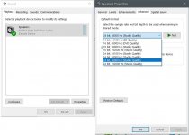
Please remember that Windows and other OSes will resample for you without warning. Please set appropriately for the desired file playback mode.
Once upgraded the Chinese DAC can be pretty nice but no matter what it won't get all the way up to Benchmark level.
Also, don't forget to try software upsampling if no hardware for it.
I put some short excerpts of a CD rip up at different bit-depths and sample rates for educational purposes. Even with my laptop soundcard, there is a noticeable difference which many people might be able to discern. But it doesn't matter all that much in terms of getting really accurate sound quality until the DAC itself is as high quality as possible. DBX
Please remember that Windows and other OSes will resample for you without warning. Please set appropriately for the desired file playback mode.
Once upgraded the Chinese DAC can be pretty nice but no matter what it won't get all the way up to Benchmark level.
Attachments
Last edited:
Hi,
What do you think of this 9038 pro card?
It's almost the same price.
Does yours has a better implementation/design?
NEW hifi TOP ES9038 ES9038PRO DAC decoder assembled board + TCXO 0.1PPM + remote control + option USB XMOS XU208 or Amanero dans Amplificateur de Electronique sur AliExpress.com | Alibaba Group
I am also Interested at 9038 pro pcb with balanced out
here same pcb but In ebay ES9038 ES9038PRO DAC DSD Decoder board HIFI Audio + TCXO + remote control | eBay
does anyone try, comment ?
Samoloko,
This board might be nice to consider also:
AK4497EQ DAC Decoder Standard Balanced Line I2S / DSD Input with Soft Control | eBay
Might be easier to get top notch performance out of this board.
This board might be nice to consider also:
AK4497EQ DAC Decoder Standard Balanced Line I2S / DSD Input with Soft Control | eBay
Might be easier to get top notch performance out of this board.
Where is the clock on that board? Hard to see from the photos.
EDIT: Crane Song Solaris DAC uses AK parts and similar upsampling to 211kHz as Benchmark. Price for a finished box is about the same:
SOLARIS
Crane Song Solaris Quantum D/A Converter | Sweetwater
Solaris clocking is reportedly better than Benchmark. Don't know about the rest.
Makes me suspect getting one working really well is probably pretty involved, similar to this one. Might be worth trying though. Are you going to get one?
Last edited:
I am also Interested at 9038 pro pcb with balanced out...
That board looks similar to the one I commented on recently in this post:
http://www.diyaudio.com/forums/digital-line-level/314935-es9038q2m-board-75.html#post5411182
It was in regard to this board:
ES9028 ES9028PRO DAC Q8 Ver2.2 HiFi Audio Decoder PCM384K / DSD128 | eBay
which although a little different than the one you are interested in, probably has similar issues to consider.
vacuphile, A second look at the AK board looks like all clocking has to be generated externally, probably from whatever is on the Amanero or similar USB card. Don't know how one would get SPDIF or TOSLINK into it. Likely a recipe for jitter, but maybe some engineering could be done to find a good solution.
Regarding external clocks, even a little cable noise or proximity to other digital signals can worsen jitter. Best to have the master clock as close by as possible.
Then there would the question of how to get SPDIF into it if one wanted that instead of USB. Maybe the best thing would be to make a clock board that mounts on the DAC board and generates mclk, bclk, and lrclk signals and then sync the output of an SRC4392 to that. Something like that. One could benefit from upsampling, good use of a slow transition minimum phase reconstruction filter, and fix the intersample over problem all at the same time.
Then there would the question of how to get SPDIF into it if one wanted that instead of USB. Maybe the best thing would be to make a clock board that mounts on the DAC board and generates mclk, bclk, and lrclk signals and then sync the output of an SRC4392 to that. Something like that. One could benefit from upsampling, good use of a slow transition minimum phase reconstruction filter, and fix the intersample over problem all at the same time.
Last edited:
Samoloko,
This board might be nice to consider also:
AK4497EQ DAC Decoder Standard Balanced Line I2S / DSD Input with Soft Control | eBay
Might be easier to get top notch performance out of this board.
Just a day ago I have finished the setup (however, very simple setup) with exactly this board. For my ears, sound is good. So, if you have any question, please, let me know - I will answer whatever I will be able.
BTW, probably, there is the sense to create another thread regarding to this board?
So when looking at inexpensive boards it appears one needs to consider the following
Ability to tap into power supplies especially to AVCC.
Ability to improve the clock and proximity of clock to chip. Closer the potentially better
Differential IV circuit built in similar to what is recommended by ESS
Lower down the scale
Ability to upgrade op amps
Quality of Linear Power supply
Ability to change the IV circuit components
Admittedly we will not get the same as reference DACs but we kind of knew that going but it is a question of how close we want to get at what price point and effort involved.
At this juncture we need to ask is it better to start with a 9028Pro DAC or is a 9038SQM as good or better. I'd be tempted to start with what Benchmark uses and getting a board that has some power supplies built in and then start hanging mods onto that. My belief is that even the power supply cable length can make differences once we get to the levels we are seeking. So proximity to the DAC and IV circuits might also be important overall.
All these Ebay boards will need some "fixin" just which one would need the least including effort and offers the most potential.
I sense that there will be a wave of newer DAC boards coming that will possibly have better layout and designs in the near future. Seeing that ESS has come out with suitable regulators of their own design, the next step would be to integrate those onto the DAC especially where it is critical. This would lower the total cost of the board as well as simplify it and possibly offer more consistent performance. The board makers are always trying to put better designs with minimum cost. Cost is a large factor when they need to sell these to integrtaors and Ebay buyers.
Last edited:
ES9028PRO might be a little better than 9038Q2M in terms of noise performance, but not distortion. Noise could be reduced at some increase in cost/complexity of IV stages by paralleling multiple 9028PRO channels and IV stages, however, costs would go up a fair amount for very modest noise reduction. Every doubling of parallel output channels decreases noise by 3db.
Also, I would probably move high-quality linear power supply to the first list of more critical items.
Opamps should be as recommended by ESS. The LME49720 opamps I used are the 3rd down on the ESS list, but the same as the LME49860 opamps Benchmark uses except only that the latter opamps are rated for use with higher power supply voltages (Benchmark uses +-18v).
Another thing Benchmark does that we are not doing is use external DSP in the form of a SHARC chip to offload some filtering from 9028PRO for some additional performance improvement. Their approach also includes the use of more clock oscillators running at different frequencies to run different parts of the circuitry. I think going that far would probably be too much for a DIY project such as we might be able to do here. Already this project is too complex for most people, it seems.
Perhaps one option to consider would be to layout our own PCB to reduce this project to stuffing a circuit board. That would remove a great deal of complexity, although maybe it would still be too much for most people. Don't know about cost if all parts had to be purchased separately. There would be fewer total parts, of course, which would probably help.
I'm not ready to go there yet though. Have to do some more work to test master mode I2S first at a minimum.
In the meantime, it might be useful if someone wanted to layout a small PCB with IV and differential combining stages. Just having something like that available would probably make upgrading much easier. Likewise for a youtube video showing how to replace the clock.
Last edited:
@borlix, Could you try measuring the voltage there and see what you get? I have no idea why some boards have an IC there and some don't.
EDIT: Regarding a 'flat' sound, I would say my board probably met that description before I started modifying it to improve sound quality. My results are that pretty much everything has to be fixed to get a really good sound like people are probably looking for and expecting from an ESS9038 of any type. No easy fix that gets it 80%-90% of the way there all at once.
@borlix, If you are looking for more info there are some posts from a little while back you might find interesting:
http://www.diyaudio.com/forums/digital-line-level/314935-es9038q2m-board-55.html#post5395485
http://www.diyaudio.com/forums/digital-line-level/314935-es9038q2m-board-63.html#post5402398
The first post above includes some links that go back a little further where I would also recommend looking.
EDIT: Clicking on the little white X's in the lower left corners of the pictures allows them to be expanded up to see a lot of detail if desired.
Last edited:
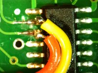
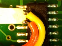
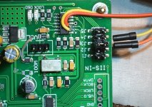
Now getting set up to start taking control over the DAC. Microcontroller I2C pins have been lifted and leads attached which can be patched back into an I2C bus socket on the underside of the board. The socket connects to the DAC I2C pins. Shiney stuff on wires is superglue to tack them down. Will unplug this microcontroller and substitute Arduino I2C leads with software real-time peek and poke serial monitor, at least to start with. From there can start coding and testing using the same app.
Attachments
- Home
- Source & Line
- Digital Line Level
- ES9038Q2M Board