WRT the Gustard and the higher harmonics it may be the result of the rather low input impedance of the Cosmos ADC, especially at the low input voltage settings. On some DACs that are sensitive to this I've observed a +15 dB increase in THD from the highest input voltage setting to the lowest input voltage setting, you might try a higher voltage setting and see if this improves. Even on the highest input voltage setting the input impedance is still only 3.5K so much lower than a typical amplifier.
Michael
Michael

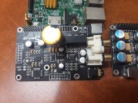
I have this hat for using with raspberry pi. Recently, it suddenly output very low signal. I mean it's difficult to hear from 3.5 audio jack (sound was too low, same audio path with RCA). I need to turn volume pot to about 12h to hear the sound. I just have basic skill to solder electrolytic capacitor.
Could you suggest what could be the reason for the issue?

Could you suggest what could be the reason for the issue?
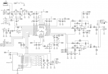
That dac looks similar in some ways to the dac board mostly used in this thread. If it helps to get some idea of certain parts of the circuitry, a schematic for the other board is attached below.
Seems like there are a few possibilities to check that might give a clue to the low volume problem. First one might be the RPi software. It could be corrupted or misconfigured.
Next thing I would probably check after that would power supply voltages on the dac board. There have to be proper voltages for the dac chip, clock, MCU, output stage, etc.
Measure at the chip being powered not just at the voltage regulator, so as to be sure that supply voltages have a good connection all the way to the load devices. Another thing to check might be to look with a magnifying glass for any cracked SMD components, cracked solder joints, basically any kind of visible defect. You might also check the AC output voltage at the dac output connectors to make sure downstream equipment isn't causing the low volume level problem. After checking the easy stuff, it might be necessary to dig deeper with a scope and or a logic analyzer.
Attachments
Last edited:
Thank you for your reply.
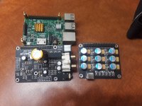
It suddenly was low volume during playing. No configuration change made. It used smpd 0.9.6. So I changed to Moodeaudio, or removed power filter board, or clean all boards by McKenic but no help.
My next check would be change pi (I have 2 pi3b), use magnifying glass, measure voltage...
It suddenly was low volume during playing. No configuration change made. It used smpd 0.9.6. So I changed to Moodeaudio, or removed power filter board, or clean all boards by McKenic but no help.
My next check would be change pi (I have 2 pi3b), use magnifying glass, measure voltage...
Attachments
It's Mornsun A0515S-2W.

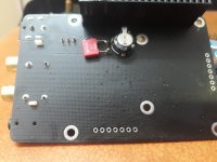
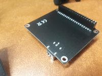
It's very difficult to measure while it's stacked. It has 5 pins and all values seems wrong. (I can check some points, there are 5VDC and it's still operating normal with LED showing.

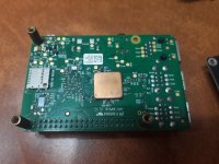
Below is the original when I bought it some year ago. Long time ago I replaced the biggest electrolytic capacitor (470UF 16v) by Audio Note capacitor 220uf63v). This is for easy to see PIN of DC-DC converter and 2 diodes (?) position.

It's very difficult to measure while it's stacked. It has 5 pins and all values seems wrong. (I can check some points, there are 5VDC and it's still operating normal with LED showing.
Below is the original when I bought it some year ago. Long time ago I replaced the biggest electrolytic capacitor (470UF 16v) by Audio Note capacitor 220uf63v). This is for easy to see PIN of DC-DC converter and 2 diodes (?) position.
Last edited:
Looking at the DC/DC converter connection diagram a few posts up from this one, the pin labelling on the pic below is backwards. The group of three pins should be 4,5,6 according to the diagram. The group of two pins, 1, 2, is where the input +5v and ground should be coming in. There is no pin 3 shown on the diagram. Therefore the input voltage appears to be 0v. Looks like the problem is not necessarily the DC/DC converter unless perhaps its input is a dead short. Maybe the DC/DC converter input voltage passes through a ferrite bead? If so, maybe the bead is bad. You should probably be able to measure with an ohmmeter from +5v on the OLED connector to pin 1 on the DC/DC converter (with the unit powered off). Is it an open circuit? If so then probably good to follow the PCB traces going to pin-1 of the DC/DC converter to see where the it is supposed to be getting its +5v from.

Last edited:
Yes, I marked the pin in that picture NOT following the spec I found later in post #7707. After removing DAC from PI, I measured again and found 5vdc at pin#1 (post #7708). So I will buy DC-DC converter and try to replace it this weekend. I will report again then.
Btw, do you have suggestions on feeding the DAC by independent +-15VDC power board such as LT3042/LT3045-LT3090...?
Btw, do you have suggestions on feeding the DAC by independent +-15VDC power board such as LT3042/LT3045-LT3090...?
Probably best to remove the DC/DC converter if you want to use external +-15 power. Pin 4 of the DC converter would be -15v, pin 6 would be +15v, and pin 5 would be ground. Looks like pins 1, 2 could be floating with respect to dac board ground plane. Depends how they designed the board. You should be able to ring out the DC converter pins pads with an ohmmeter to double check which pin or pins go to the dac PCB ground plane, and which converter pins go to the output stage opamp pins 4,8.
Well, I've just replaced DC-DC converter but it's able to play just a short time (one or two songs). Then there was just constant sound woooooh. I've tried to restart but it's not able to up. I found the converter was super hot, cannot touch.
So there are smth wrong but I do not know. Is it because of input voltage was less than 5vdc so the converter must boost it up to have +-15vdc output?
So there are smth wrong but I do not know. Is it because of input voltage was less than 5vdc so the converter must boost it up to have +-15vdc output?
The large cap is 220uf 63v. The original spec is 470uf16v. I have replaced it by 470uf25v and still hang at start up (smpd os plays short audio during boot and the LED on DAC will turn off after finishing it normally) but now the LED keeps ON and converter getting hot quickly. So weird.
The large cap is 220uf 63v. The original spec is 470uf16v.
So the cap isn't on the output of the DC-DC? I ask because its a +/-15V unit so the stock cap would need to be 35V rated if between the rails. If the cap's only on one rail, what would the purpose be of only decoupling one of a pair of rails?
The datasheet for the Mornsun DC-DC shows an application with capacitors on both output rails.
I removed DAC from Pi and power it on, measure it. Input pins 1, 2 are ok (5vdc and 0v).
Output pin 4 is about -1.4vdc, pin 6 is about 5vdc only. Power it off, and check ohm values from pin 1 to 4, 5, 6 are infinitive. Pin 2-4 are 130ohm, 2-5: 0ohm, pin 2-6: 4300ohm.
Does this indicate that DC-DC converter failed again?
Output pin 4 is about -1.4vdc, pin 6 is about 5vdc only. Power it off, and check ohm values from pin 1 to 4, 5, 6 are infinitive. Pin 2-4 are 130ohm, 2-5: 0ohm, pin 2-6: 4300ohm.
Does this indicate that DC-DC converter failed again?
Here is the DS for the DC-DC : note the recommended output caps are rather small values (470nF) :
https://www.mornsun-power.com/html/pdf/A0515S-2WR2.html
https://www.mornsun-power.com/html/pdf/A0515S-2WR2.html
- Home
- Source & Line
- Digital Line Level
- ES9038Q2M Board