Only in your opinion. What I wrote about the cables was entirely factual. Nothing was made up.
Did I actually claim that you made something up?I wrote to explain to people reading along what actually happened back then.
Perhaps it's time to relearn that the plain meaning of "you are on my ignore list" is "you are not really on my ignore list". Got it.An explanation was appropriate since you keep trying to misinterpret my words as something other than their plain meaning.
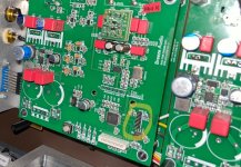
If you happen to have a multimeter you can trace where they are connected to.Some of you can help me about the function of this four pins?
Some of these boards support an LCD display and optical encoder for the user interface. My guess is J4 if for the display and J5 is for the encoder. You might be able to figure it out further by getting the data sheets for U5 (display driver?) and U6.
Here's an example from an Ebay listing:
Here's an example from an Ebay listing:
Attachments
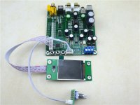
As I said before Breeze DAC board seems to have a common connector for I2C & encoder as in this very similar dac (ES9038Q2M Mini DAC). So I'll keep my bets on either SWD or UART.
After seeing your example I would have to agree.(ES9038Q2M Mini DAC). So I'll keep my bets on either SWD or UART.
Thank you, in the link is the 12v version of the same dac.As I said before Breeze DAC board seems to have a common connector for I2C & encoder as in this very similar dac (ES9038Q2M Mini DAC). So I'll keep my bets on either SWD or UART.
At the time was possible to choose between the board with 12v or dual 15v, I have both versions, but basically they are similar.
I was trying to figure if it is possible to use filter change from that pins without using the display/ir.
The last displays that I bought didn't work anymore with the apple remote control and on that specific pins there aren't much indication.
On the boards I have this is done with 3 jumpers. However, if you look at the filter performance graphs on the ES9038Q2M data sheet, all these filters begin to roll off at 20 kHz, or higher, which essentially makes their effects inaudible. I did listening tests for a few days and could not hear any difference. Prior to that I was considering installing a front panel switch for filter selection but determined it unnecessary.I was trying to figure if it is possible to use filter change from that pins without using the display/ir.
Did a lot of experimenting with ES9838Q2M dac boards. People who did hear a difference between filters tended to choose filters to compensate for dac performance issues, and or for other reproduction system issues. With the lowest distortion and noise dac and system implementations, the default linear phase filter tended to sound the best. Also, FR droop of the 'slow' roll-off filters can extend well into the upper audio band. Phase is affected by filters that are not linear phase.
Last edited:
If a DAC is causing audible difference, it must be a bad design because even the cheap DACs these days have distortion / noise level below audible threshold.Did a lot of experimenting with ES9838Q2M dac boards. People who did hear a difference between filters tended to choose filters to compensate for dac performance issues, and or for other reproduction system issues. With the lowest distortion and noise dac and system implementations, the default linear phase filter tended to sound the best.
That's a legend, unless you can cite the test details and results.because some people can hear the differences.

IIUC, AGND_L and AGND_R are probably the grounds for the analog output switched resistor network. AGND might be the ground for VCCA, which includes analog RF such as clocking. AVCC_L and AVCC_R are the reference voltages for the analog output switched resistor network. You will probably find that the sound of the dac is affected by the type of voltage regulator used to supply AVCC_L and AVCC_R (L and R refer to the left and right channels). Some people like to use opamp buffers for AVCC regulators, rather than voltage regulator chips, say, maybe such as LT3042. IIUC Topping used opamp buffers for that in their top of the line D90 ES dac. Using separate regulators for AVCC_L and AVCC_R will probably help improve stereo separation.
Hi guys, I'm new to the forum and hope I don't mess it up.
I read lots of pages to this topic, but didn't came accross usable infos for me to this DAC.
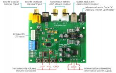
I'm not too deep into electronics, but I like to build a decent entry DAC-Streamer with the audiophonics board which was posted (Post 7462) a few pages earlier (see attachement).
Does anybody have pictures and maybe descriptions from upgrades you did to the DAC? Like easy ones 🙃
For example I don't know how to connect a toroidal transformer to the DAC. Is it just connect up the transformer directly to the board correctly and change the solder point of the "Power Selection" (J6)? Or do I need other parts between the transformer and the DAC board?
Other Topic: DSD
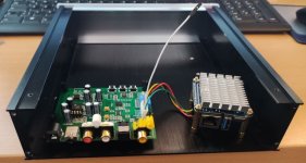
I tried to play DSD direct to the DAC.
I used a NanoPi Neo3 with volumio installed. I could choose between I2S and SPDIF.
Both Outputs are working fine, PCM LED and LOCK LED are ON when I play music.
I also tried to play DSD and it worked (also with both outputs), but I never got the DSD LED to light up.
Volumio showed it's playing the DSD File.
Lookes like the DAC doesn't recognize that there is played DSD or volumio is resampling it to PCM. But I configured it to "DSD Direct" in the playback settings.
Does anybody got DSD to work?
Thanks for all the work some put into this for sharing information about these DACs!
greetz
marcus
I read lots of pages to this topic, but didn't came accross usable infos for me to this DAC.
I'm not too deep into electronics, but I like to build a decent entry DAC-Streamer with the audiophonics board which was posted (Post 7462) a few pages earlier (see attachement).
Does anybody have pictures and maybe descriptions from upgrades you did to the DAC? Like easy ones 🙃
For example I don't know how to connect a toroidal transformer to the DAC. Is it just connect up the transformer directly to the board correctly and change the solder point of the "Power Selection" (J6)? Or do I need other parts between the transformer and the DAC board?
Other Topic: DSD
I tried to play DSD direct to the DAC.
I used a NanoPi Neo3 with volumio installed. I could choose between I2S and SPDIF.
Both Outputs are working fine, PCM LED and LOCK LED are ON when I play music.
I also tried to play DSD and it worked (also with both outputs), but I never got the DSD LED to light up.
Volumio showed it's playing the DSD File.
Lookes like the DAC doesn't recognize that there is played DSD or volumio is resampling it to PCM. But I configured it to "DSD Direct" in the playback settings.
Does anybody got DSD to work?
Thanks for all the work some put into this for sharing information about these DACs!
greetz
marcus
Attachments
Don't connect a power transformer directly to the dac board. That would damage the board.
The DSD light on the board is operated by firmware programming in the MCU. The MCU reads the status of the DAC chip over I2C bus. Sending DSD over SPDIF requires encoding the DSD in DoP format, a kind of PCM format in which the DSD is encoded. The DAC chip can recognize and decode DoP, but hard to say if that's what its receiving without reading the DAC's I2C registers. Easier to see if its really DSD if using the I2S bus input into the DAC, and an oscilloscope is available to look at the waveforms.
The DSD light on the board is operated by firmware programming in the MCU. The MCU reads the status of the DAC chip over I2C bus. Sending DSD over SPDIF requires encoding the DSD in DoP format, a kind of PCM format in which the DSD is encoded. The DAC chip can recognize and decode DoP, but hard to say if that's what its receiving without reading the DAC's I2C registers. Easier to see if its really DSD if using the I2S bus input into the DAC, and an oscilloscope is available to look at the waveforms.
Last edited:
I don't have a transformer available, but thinking about getting the right parts to connect a toroidal transformer, because this seems the preferred powering of the DAC.Don't connect a power transformer directly to the dac board. That would damage the board.
Can you point out the parts on audiophonics just as a suggestion?
Okay. I'll try DoP over SPDIF. This is more a configuration thing with trial and error. I don't have an oscilloscope.The DSD light on the board is operated by firmware programming in the MCU. The MCU reads the status of the DAC chip over I2C bus. Sending DSD over SPDIF requires encoding the DSD in DoP format, a kind of PCM format in which the DSD is encoded. The DAC chip can recognize and decode DoP, but hard to say if that's what its receiving without reading the DAC's I2C registers. Easier to see if its really DSD if using the I2S bus input into the DAC, and an oscilloscope is available to look at the waveforms.
I wasn't aware that I have to send DoP thru SPDIF.
Thanks! :-D
- Home
- Source & Line
- Digital Line Level
- ES9038Q2M Board