LT3042 OUTPUT Impedance(2/2): アナログ回路のおもちゃ箱
Above is a link to a Japanese designers site giving graphs of the zout of his various designs of LT3042 regulators. The last graph is one from a linear audio test of different linear regulators. The Jung based regulators are an order of magnitude better on output impedance.
Not sure where you got here the idea of Jung regulator, it could be certainly as good as, or beter, than a specialized IC, although I doubt it would happen in real life, due to the size and difficulty of placing in the DAC VCC pin proximities.
What was suggested here was to use for AVCC a low noise op amp buffer (+1 gain) with the input and output filtered by RC cells. This is what apparently Topping is using too, note the 3.3ohm resistor at the op amp outputs. There goes the low output impedance
 .
.Speculating is not a bad thing, as long as it's not presented as the absolute truth
Can I have your input on how adding up several DAC outputs affects THD? I can comprehend that noise will go down by 3dB by adding 2x the amount of DAC outputs - but what about THD in this regard?
THD should not be affected in a first approximation, THD+N (which is 1/SINAD) and IMD (which also contains the noise contribution) is. Actually, my THD was always around -125dB, with all I/V versions, after optimizing H2 and H3 using the ES9038 registers.
Last edited:
Not sure where you got here the idea of Jung regulator, it could be certainly as good as, or beter, than a specialized IC, although I doubt it would happen in real life, due to the size and difficulty of placing in the DAC VCC pin proximities.
What was suggested here was to use for AVCC a low noise op amp buffer (+1 gain) with the input and output filtered by RC cells. This is what apparently Topping is using too, note the 3.3ohm resistor at the op amp outputs. There goes the low output impedance
I'll refer to this post
I'm now pretty sure that the output node is at mentioned point A - so the 3R3 is inside the feedback loop. Still, this was only deducted from the photos available. Several people looked at this and confirmed it. Not 100% sure yet though, but having 3R3 in series with the regulator's would be kind of insane, I have to admit.
Last edited:
Oh, I thought you were referring to the circuitry in the D90 (There's a 3R3 in there as well, that's why I thought you were referring to that). If not, then please disregard.
As I said I'm not actually using anything yet. The plan is to use a LT3042 with 22u bypass C on the voltage setting resistor to lower low frequency noise (as advised in the datasheet). Then this will be filtered by an RC filter with the C as close as possible to the noninverting input of the OPA1612.
As I said I'm not actually using anything yet. The plan is to use a LT3042 with 22u bypass C on the voltage setting resistor to lower low frequency noise (as advised in the datasheet). Then this will be filtered by an RC filter with the C as close as possible to the noninverting input of the OPA1612.
So the op amp is just extra, a LT3042 is used, anyway. Then I don't really understand why using an extra op amp, unless it's some sort of marketing requirement, to follow other already successful designs. And that, for a ES9038QM2 which is already 6dB worse than a ES9038PRO, in the SNR department.
I already tried to explain where I was coming from this here. Please don't take it as a personal insult, but reading other people's output is not your strong side, is it?
PS: The marketing argument is clearly not applicable to me. I always release my designs and software as open source. Take a look at my website and you might understand. Pulseaudio crossover rack for example has probably a few hundred man hours in it. I got commercial requests but I pissed off all of them by mentioning that any improvements would make it back upstream into my codebase. Go figure...
PPS: For me my IT day job pays the bills (might have heard that elsewhere)
PS: The marketing argument is clearly not applicable to me. I always release my designs and software as open source. Take a look at my website and you might understand. Pulseaudio crossover rack for example has probably a few hundred man hours in it. I got commercial requests but I pissed off all of them by mentioning that any improvements would make it back upstream into my codebase. Go figure...
PPS: For me my IT day job pays the bills (might have heard that elsewhere
)
Last edited:
So you would think a regulator is unable to sink current? What do you think will the regulator output big (ceramic) capacitor do? And after all, how much current and how fast do you need to source/sink?
Sorry, but without any solid data about the AVCC source/sink current requirement, you are on a wild assumption road. Solid engineering is to identify the requirement and design a solution, not to design a solution to a hypothetical, not clearly identified problem.
Sorry, but without any solid data about the AVCC source/sink current requirement, you are on a wild assumption road. Solid engineering is to identify the requirement and design a solution, not to design a solution to a hypothetical, not clearly identified problem.
Let me rephrase: It cannot actively sink current.
On all the other stuff: I have to admit - that's where I am. But there is next to zero proof out there, nobody has conducted any measurements on error voltages on the AVCC lines AFAIK. All the people denying the advantages of opamp power supplies for AVCC don't have proof either. So where too look?
That's when I decided to try a "cost no object" approach and the technical reasoning behind it is just theory, but well researched (as far as my knowledge admits) and calculated/simulated theory.
Btw. I'm all yours regarding placing components as close as possible together, so loop currents cannot introduce/receive EMI. I have an (admittedly non-formal) education in this stuff being a licenced radio amateur and having worked at an EMI lab for over a year in a (very very) extended internship (when I was young).
On all the other stuff: I have to admit - that's where I am. But there is next to zero proof out there, nobody has conducted any measurements on error voltages on the AVCC lines AFAIK. All the people denying the advantages of opamp power supplies for AVCC don't have proof either. So where too look?
That's when I decided to try a "cost no object" approach and the technical reasoning behind it is just theory, but well researched (as far as my knowledge admits) and calculated/simulated theory.
Btw. I'm all yours regarding placing components as close as possible together, so loop currents cannot introduce/receive EMI. I have an (admittedly non-formal) education in this stuff being a licenced radio amateur and having worked at an EMI lab for over a year in a (very very) extended internship (when I was young
).
Last edited:
On all the other stuff: I have to admit - that's where I am. But there is next to zero proof out there, nobody has conducted any measurements on error voltages on the AVCC lines AFAIK. All the people denying the advantages of opamp power supplies for AVCC don't have proof either.
Don't you know it is impossible to "prove" a negative statement?
But, after all, the "proof" is in the pudding. You can, of course, make whatever decisions you think are appropriate, including for CYA, but don't you think the results I got without a stinkin' op amp buffer are good enough for audio reproduction?
I don't know yet, never did any listening tests - proper blind A/B tests - yet.
There's a problem with all the arguments that arise again and again. Guys like you argue that these are unnecessary because measured performance is "the proof that it's good enough" - so you will not do any of these tests.
The opposite side refuses to do these test as well, mostly following the argument that these are either to complicated to set up or they are irrelevant because casual listening is more appropriate.
So this way we will never go anywhere... As I said - I will first try to come up with a "cost no object design" and then do proper listening tests... Stay tuned if you're interested...
PS: accusations and insults, be they direct or wrapped in some way, form or other, will not bring us along. Let's be kind, that for starters will go a looong way...
Not sure if you follow what I am saying, there was no insult. "CYA decision" stands for "Cover Your ***" and you would not be the first following this kind of logic. If I would have a dollar for each time I've seen such decisions made by otherwise compentent engineers (not only in Electronics) I could retire today.
"Stinkin' op amp buffer", it is exactly this, in this particular case. Use it if you feel like, but don't expect anybody but the Golden Ears to support this decision. All I can do is to tell where this op amp buffer myth is coming from... It was a design decision in the ESS demo boards, and some knucklehead decided this decision should go in the Golden Ear bible book, considering the ESS application engineers the Apostles of the High End Audio Order. Once again, if I would have one dollar each time I've seen compromised demo board designs (the last one is the TI ADS127L01 demo board, they went so far to fudge the software so that the affected parameters are not measured/shown) I would be rich.
"Stinkin' op amp buffer", it is exactly this, in this particular case. Use it if you feel like, but don't expect anybody but the Golden Ears to support this decision. All I can do is to tell where this op amp buffer myth is coming from... It was a design decision in the ESS demo boards, and some knucklehead decided this decision should go in the Golden Ear bible book, considering the ESS application engineers the Apostles of the High End Audio Order. Once again, if I would have one dollar each time I've seen compromised demo board designs (the last one is the TI ADS127L01 demo board, they went so far to fudge the software so that the affected parameters are not measured/shown) I would be rich.
I was referring to a capacitor being a passive component. And a regulator output as being an active component.
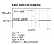
Where do you think the asymmetries shown here come from (taken from the LT3042 datasheet)?
And how do you know that step response is not good enough? Have you measured 200mA step variations on the AVCC pins? Less? More? Or at least the load regulation required on the AVCC pins?
Last edited:
I just though you might be interested in improving things but I'm getting the impression you don't.. again. In real life I have used Jung and opamp buffers on all of my builds. Remote sense is your friend. Is small size more important than performance?
I don't endorse the Topping design at all (I'm not privy to their schematic) or indeed the ESS regulator chip for their DACs, though it ain't bad in the SGD1. Where did you get that idea from?
BTW there is no magic to the Jung regulator that a bit of wideband opamp rail decoupling to an opamp buffer and can't achieve in this context. The Jung regs unfiltered supply bootstrap causes its own problems along with its high dropout voltage. A well designed opamp buffer isn't handicapped by the CCS or dropout imperfections. Check out the Flea clock supply if you want really low noise, low output z and small size.
Until the quantity of load current related noise on the DAC supply pins is measured and compared with the inherent supply noise who can say how large or small the benefits will be. Also, if there is any correlation between supply noise in all its forms and DAC THD, IMD and SINAD then output z of the supplies at least needs to be investigated. I wish I had the kit you have to do this but this isn't my day job. Perhaps you have observed this correlation already and would be prepared to share your findings? If not, then can you tell us what measurable reason you have to pursue lowest possible noise in the DAC supplies in the first place?
John
I have a day job too, and I have no idea what "kit" you are talking about. I can afford to not care about any investigations if the end to end results are better than anything that can be measured today, with the latest AP or whatever. I'll leave these investigations for those with inclinations for such details and more time in their hands than myself. But then I would expect hard data, not anecdotic reports of "sounds better".
One thing I find weird is the very little penetration that the ES9311 regulator has, both in commercial and DIY DAC implementations. ESS guarantees the DAC performance when using these regulators for AVCC, the regulator spec looks excellent, and it is a dual regulator at half the price of a single LT3042. I know I did not use it because it was not in stock at Mouser when I was designing the board, then I did not find any good reason to use anything else beyond the ADM7154. If I would have to change anything in the AVCC supplies, this is what I would try in the first place.
Jung regulators, not so much due to, as I already said, size and impossibility to place them close to where they are needed. I would not be comfortable placing the AVCC regulators 2-3" away from the AVCC pins (like they did in the AK4499 demo board), but color me blue, that's me. In my book, this would be a step back, not an improvement, although I might be wrong. Though, such an experiment would be, for me, too expensive to make any sense. Unfortunately an ESS9038PRO implementation is not something that can be breadboarded and get quick results.
Last edited:
Not sure if you follow what I am saying, there was no insult. "CYA decision" stands for "Cover Your ***" and you would not be the first following this kind of logic. If I would have a dollar for each time I've seen such decisions made by otherwise compentent engineers (not only in Electronics) I could retire today.
"Stinkin' op amp buffer", it is exactly this, in this particular case. Use it if you feel like, but don't expect anybody but the Golden Ears to support this decision. All I can do is to tell where this op amp buffer myth is coming from... It was a design decision in the ESS demo boards, and some knucklehead decided this decision should go in the Golden Ear bible book, considering the ESS application engineers the Apostles of the High End Audio Order. Once again, if I would have one dollar each time I've seen compromised demo board designs (the last one is the TI ADS127L01 demo board, they went so far to fudge the software so that the affected parameters are not measured/shown) I would be rich.
I was just referring to the wording... Stinkin' and such. Do we need that? I tell my 4 year old nephew to not use such words for a reason. It's not helping us along and tone IS important IMHO
syn08
I deleted that post before you replied because I can't be bothered with you. You have probably noticed how good you are irritating people. You offer little but criticism and faintly veiled insults, I guess it is what gives you most satisfaction and self esteem, but it is alien to the spirit of this DIY forum. Given your obvious ability it is such a disappointment.
John
I have a day job too, and I have no idea what "kit" you are talking about. I can afford to not care about any investigations if the end to end results are better than anything that can be measured today, with the latest AP or whatever. I'll leave these investigations for those with inclinations for such details and more time in their hands than myself. But then I would expect hard data, not anecdotic reports of "sounds better".
One thing I find weird is the very little penetration that the ES9311 regulator has, both in commercial and DIY DAC implementations. ESS guarantees the DAC performance when using these regulators for AVCC, the regulator spec looks excellent, and it is a dual regulator at half the price of a single LT3042. I know I did not use it because it was not in stock at Mouser when I was designing the board, then I did not find any good reason to use anything else beyond the ADM7154. If I would have to change anything in the AVCC supplies, this is what I would try in the first place.
Jung regulators, not so much due to, as I already said, size and impossibility to place them close to where they are needed. I would not be comfortable placing the AVCC regulators 2-3" away from the AVCC pins (like they did in the AK4499 demo board), but color me blue, that's me. In my book, this would be a step back, not an improvement, although I might be wrong. Though, such an experiment would be too expensive to make any sense to me. Unfortunately an ESS9038PRO implementation is not something that can be breadboarded and get quick results.
I have a hunch that the ES9311 is just a dual opamp reg in disguise... That much i infer from the product brief, no datasheet available unfortunately.
- Home
- Source & Line
- Digital Line Level
- ES9038Q2M Board