Regarding a suggestion of Jan Didden's Silent Switcher, it can be a problem for dacs depending on the input voltage source used for the switcher. If using a wall wart then common mode switching noise from that will appear as ground noise at the dac. That's because silent switcher does not isolate input and output grounds. That common mode ground noise can couple into differential mode signals and introduce audible distortion. (I know because I tried it, heard the distortion, used measurement to trace it to the source, then tried an alternate 5v source which was a linear 5v supply. Measured noise and audible distortion problem went away. Most of the wall wart noise in that case was spread across a band, approximately 1MHz - 2MHz.) Other than the wall wart problem SS was pretty good, although I did prefer a linear supply for overall sound quality. Still have two of SS, never tried them again.
Last edited:
I was kind of expecting this. I have tested my dac with SilentSwitcher powered from batteries or from USB. No visible difference in distortion measurements or even in THD+N.
With regards to you hearing this distortion I can only admire your hearing capabilities at levels below -110dB.
With regards to you hearing this distortion I can only admire your hearing capabilities at levels below -110dB.
Not everything that is audible shows up well on an audio FFT. Nothing new about that.
Possibly interesting, a discussion of noise floor modulation at: ESS Sabre Reference DAC (8-channel) Just mention it because most people don't think to measure for it and or don't believe it could ever be audible to anyone. Others, such as ESS do think it can be audible to some.
Possibly interesting, a discussion of noise floor modulation at: ESS Sabre Reference DAC (8-channel) Just mention it because most people don't think to measure for it and or don't believe it could ever be audible to anyone. Others, such as ESS do think it can be audible to some.
Last edited:
Doesn't have to be distortion, could be noise. Especially if noise is audio signal correlated. Nothing new about that.
You already know what this is, starts with m... Correlated noise is not noise. Noise is fundamentally uncorrelated.
Not everything that is audible shows up well on an audio FFT. Nothing new about that.
Yes, there's indeed nothing new about this universal argument.
Noise can be defined as nondeterministic, which is to say, not predictable in any way. As soon as we have frequency shaped noise we know something about it that is predictable.
Noise can also be defined as anything not consisting of a desired signal. No surprise that a a definition of noise can be put forth that doesn't apply to noise, whatever it is, which follows signal level.
EDIT: Think I will give this a rest. Arguments that never lead to any useful conclusion are more like political debates.
Last edited:
You already know what this is, starts with m... Correlated noise is not noise. Noise is fundamentally uncorrelated.
The moderators should tag some of these posts in a similar fashion that Twitter tagged Trump's tweets. Something like: "WARNING!!! This post contains insults."
Noise can also be defined as anything not consisting of a desired signal.
Whoever taught you this definition should be called a clueless chap.
And "frequency shaped noise" refers to the noise spectra (aka "noise spectral density") which is not flat and frequency unbound (aka "white"), not to noise that has any signal correlation.
Good idea to give it a rest
 .
.
Last edited:
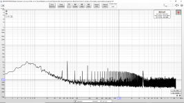
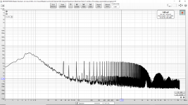
Attached, 20Hz-10KHz. Bottom (blue) is the LNA input shorted, mid (red) is a 50ohm resistor, top (purple) is the 2.5V VREF noise, ADC running with a 1KHz FS input. The LNA and the ADC are not shielded in this case, hence the rather large mains harmonics. LNA gain is 60dB.
So I built and tested my first attempt at a low noise pre-regulator. This is intended to power the reference and LM4562 AVCC_R/L filter type supplies.
It consists of a CRC prefilter, followed by a shunt regulator followed by a capacitance multiplier. The shunt regulator is made of 3x parallel large die/low base resistance devices. (And the Zener, low value metal film resistors and large low ESR capacitors.) The capacitance multiplier uses 3x parallel large die/low base resistance devices, low value metal film resistors and large low ESR capacitors.
I would appreciate your assistance in interpreting the results from a noise standpoint.
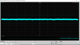
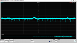
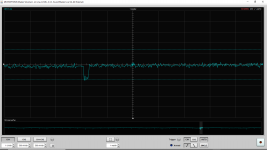
I have attached the voltage waveform and spectrum from the LNA input shorted measured immediately before the voltage waveform and spectrum from the preregulator output. The preregulator output is running at 50 mA. Waveforms are 1uV per division.
I wonder what the sudden downward pulses are in the output. They are strangely regular in spacing. ???
Attachments
Last edited:
No need to further show the scope noise, that's largely irrelevant, the noise spectra are good enough, once you calibrated and confirmed the noise scale.
What can I say, if your current noise spectra are at the same scale as your previous measurements, then your current results are suspiciously good. I am having a hard time believing that a linear power supply of whatever type and quality may have a noise of 0.5nV/rtHz. Besides, these values are much less than what you showed earlier as the LNA input shorted noise (some 2.5nV/rtHz). Are you sure your LNA is AC coupled with the power supply?
As of the "pulses", I don't know. They could be driven by your USB measuring setup, since USB has 1KHz and 8KHz frames events, but I am speculating.
No need to further show the scope noise, that's largely irrelevant, the noise spectra are good enough, once you calibrated and confirmed the noise scale.
What can I say, if your current noise spectra are at the same scale as your previous measurements, then your current results are suspiciously good. I am having a hard time believing that a linear power supply of whatever type and quality may have a noise of 0.5nV/rtHz. Besides, these values are much less than what you showed earlier as the LNA input shorted noise (some 2.5nV/rtHz). Are you sure your LNA is AC coupled with the power supply?
As of the "pulses", I don't know. They could be driven by your USB measuring setup, since USB has 1KHz and 8KHz frames events, but I am speculating.
It is AC coupled with a Nichicon UES capacitor.
I will double check everything again. However in this case the LNA is inside a steel tin which is inside a heavy steel pot. The preregulator prototype that is being tested is isolated from the steel tin but is sitting on the top of the steel tin inside the heavy steel pot. It liberally uses large low ESR capacitors and large die transistors. (Basically the same large die transistors used at the input of the LNA actually. The same die layout and process but for some reason they have a different part number.)
So this time I don't have cables going all over the place to the DAC. And I don't have multiple power supply cables going to the DAC. This is just the preregulator alone inside the steel pot being using for shielding.
The cables and what they are attached to (measurement and power) going to the DAC appear to be a big limiting factor. My environment is not ideal but I am doing what I can to control noise from the environment. When the LNA is shorted inside the steel pot the results are much better (as opposed to being shorted several feet away soldered to the DAC board with all the power supply cables attached to the DAC.) Less opportunity for grounding problems.
Right now I don't have steel shielding large enough to contain both the DAC and the LNA.
Last edited:
So going back to post 6498 (when I was testing and verifying the LNA inside the steel tin and steel pot) the LNA noise results are very very similar to the work today. I also just double checked the LNA gain settings and everything looks ok (60 dB and right scale factor).
I started with published low noise designs and then I used paralleled lower noise transistors, lower value resistors and much better bypassing. (Bypassing in more areas, large and lower ESR.) Also this is three stages. (CRC, shunt and capacitance multiplier.) The input is also clean to start with, but what I am really concerned with is noise generated by my regulator and later reference itself. The power input to my DAC is much cleaner than the output of the stock LM7805 and AMS1117-3.3, for example. I used several nice regulators to power the DAC and it did not matter at all since the stock LM7805 and AMS1117-3.3 are orders of magnitude more noisy.
The idea is that with discrete components I can do several things that a monolithic die can not:
- I can use specific process and design low noise transistors that are each the die size of an entire monolithic regulator or reference die. Then I can put 3x in parallel. (Which I did everywhere I used a transistor.)
- I can use lower value resistors and burn more current deliberately.
- I can also use vastly more capacitance and number of capacitors to bypass almost as well as I would like anywhere in the circuit.
Last edited:
^^^
I'm afraid you keep shooting in all targets and running around in circles. This makes helping you very difficult. If you want to believe that a DC regulator can achieve 0.5nV/rtHz noise, that a discrete regulator can necessary exceed specialized IC performance metrics, that all your measurements are flawless, and you can choose at any moment one at your convenience, for reference, etc... then I'm afraid you are beyond my help abilities.
You'd be much comfortable with Markw4 and his posse advice, they will not quibble over inconsistent measurements results. I'm out for the time being.
Nichicon UES appears to be a bipolar electrolytic type. At some frequency it will probably look more like an inductor than a capacitor. Larger case sizes and uF values may turn inductive at lower frequencies. Suggest you might try a more suitable capacitor for RF use.
Perhaps you have an RF generator you can use to check the frequency response of the test setup, ideally up to and above the dac clock frequency? If not, perhaps good to try the scope without the low noise preamp to see if there is wideband consistency between readings with and without the added gain stage. What is the scope bandwidth specification?
EDIT: Completely agree 0.5nV/rtHz is not credible. Something has to be wrong somewhere, maybe more than one thing.
EDIT2: Your FFT display shows you are using exponential averaging. You understand that the processing averages out displayed noise?
EDIT3: That a soundcard scope program you are using?
Last edited:
Kozard,
I have to largely agree with syn08. Your noise graphs look suspicious. And without schematics of you regulators it is virtually impossible to analyse your results. Anyhow I suggest you "calibrate" you LNA/REW by shorting the LNA input with resistors of varying resistance (e.g. 100ohm and 1kohm). You should see straight noise line corresponding to the thermal noise of the resistor. 100ohm is about 1.3nV/√Hz, 1kohm is about 4nV/√Hz.
And as syn08 pointed out your approach seems to be well inline with the thread.
- Home
- Source & Line
- Digital Line Level
- ES9038Q2M Board