Except transformer voltages are AC, so no +- signs needed at that point.
I should probably mention why I use 18v windings if I want +-15v rails. The reason is that regulators often tend to regulate better with a few volts of drop of across them. Sometimes that better-ness comes out in the audio.
In addition, regulators often to tend to vary in performance with current draw. Sometimes dumping some extra current into a load resistor may have an effect that can be heard in the audio. The load resistor thing is an old trick, but sometimes forgotten. IME it isn't always helpful, but it sometimes can be.
Hi,
Recently I bought several DAC boards very similar to the first post in the thread and was a bit disappointed of high 3-rd harmonic level, about -80 db.
The curious thing is only the 3-rd harmonic exists, the other harmonics are near the noise level.
So I started to find a way to eliminate the 3-rd harmonic as it’s obviously much higher than the DAC (chip itself) can produce. There were several hypothesis. One of them is that cheap board takes voltage from the DAC output directly and has no an I/V conversion at all (I took off the schematic diagram from the board). Replacing electrolytic caps, opamps and other minor components didn’t help. I’m now not in the position to re-solder the board to add an I/V converter just to check the hypothesis, but reading the ES9038Q2M datasheet I found some registers that can “compensate” the harmonics (by generating reverse phase artificial distortions probably).
The board includes an STC15W480AS MCU to control the DAC. So I’ve rewrote the MCU firmware to set those compensation register to “proper values”.
I reached a kind of success and could decrease the harmonic level by 10-12 db and continue trying.
For now I can read/write individual the DAC registers via UART (from PC directly) at least.
If somebody wants to know the details, welcome, I would be happy to share my experience.
I just wouldn’t like to bother all the forum participants with the MCU specifics.
Hi Serge,
Looks like so far you are trying the fix the symptom rather than fix the underlying problem.
The real problem is that the board comes with a voltage mode output stage. The dac chip really is quite nonlinear operating in voltage mode. What it needs is a proper I/V output stage, some filtering of RF out of the analog output signals, and much better voltage regulation for AVCC_L and AVCC_R. Some recommended circuits are attached to post #3003 of this thread. I might change some of it a little now, but those are a good start to better dac.
In addition, there is some old documentation on the ESS website that exists from before they decided to go the NDA route. The page is at: ESS Technology :: Downloads ...and probably the first thing to carefully read is: http://www.esstech.com/index.php/download_file/view/69/267/
One thing I would say is that single opamp output stage they show in that document does not seem to work with the newer dac chips such as ES9038Q2M.
Also, there are other things we now know about using these dac chips that were not fully understood back when the document was written.
Regarding your offer to share what you have done with the existing MCU, please do. I'm sure there are some lurkers who would find it interesting.
EDIT: By the way are you sure the MCU part number isn't STC15W408AS (with the 0 and 8 transposed)?
Last edited:
>Looks like you are trying the fix the symptom rather than fix the underlying problem.
Thank you for the reply, Markw4!
Yes, but to fix the real problem I would need a completely new board.
-Do you know any I/V converter that could be ordered separately?. If so I could try to splice the 2 boards (DAC + i/V) anyhow
- What do you think if I change the balanced voltage to (single) unbalanced I/V using the same opamp? I see it would be a phase inverting stage, but there is only one dual opamp on the board (for left and right channels accordingly)
>By the way are you sure the MCU part number isn't STC15W408AS (with the 0 and 8 transposed)?
You are right STC15W408AS. Typo :-( There is just no such “...480...”
I was asked by some of the guys in this thread to make a through hole output stage board that could be fabricated by hand and attached to the dac board. The documentation is still in my dropbox: Dropbox - Output Stage Instructions.zip - Simplify your life ...the rtf file contains some pics, don't know why but some people get warnings it is suspicious. Its just pics and some text, nothing executable.
Personally, I would have preferred to do it in SMD. There are some nice little prototyping adapters called surfboards: SURFBOARDS FOR I.C.s Model 9081 Surface Mount Breadboard
Also maybe good to know about, there is always RF leaking out of dac chip analog outputs. With ES9038Q2M some excess heating of output stage opamps was noticed by me and by some others when the opamps were too close to the dac chip. For through hole output board, I used twisted pairs of wire wrap wire run along the dac board ground plane to the I/V inputs on the output stage board. That seemed to provide some distributed differential capacitance between dac + - output phases and also some capacitance to ground. Not much though. No opamp heating was noticed in that case, and there did not seem to be a gain peaking problem in the I/V opamps that can be expected with too much input capacitance.
EDIT: To directly respond to your question about after market output stage boards that could be used with the dac board, none exist that I know of. You aren't the first person to express interest either. Nobody ever found one.
EDIT 2: Daniel recently posted Gerbers and source files for an output stage board he laid out. There is a freeware non-commercial version of the PCB program he used, so the board design could be edited at no cost.
Last edited:
What do you think if I change the balanced voltage to (single) unbalanced I/V using the same opamp?
You could try it I guess. Correct opamp to use is OPA1612. If you took dac inverted output for each channel and inverted once more in an unbalanced I/V stage, the inversion would gone. Problem might be some distortion and noise that is supposed to be canceled out in a balanced I/V output stage. Also, the recommended differential summing stage for single ended outputs also does some more filtering. If you skip that stage, the filtering is probably still needed.
That said, IME and IMO the differential summing stage is often where residual RF causes more noise and audible, although perhaps nonstationary, distortion (nonstationary in relation to typical audio FFT acquisition time frame).
Not sure about the unused output. Normally they are tied to a virtual ground at AVCC/2 volts. If you want to experiment you might leave it open, then try biasing it to AVCC/2 (~1.65v) at DC with some resistors and bypassing AC to ground with a capacitor, something like that. Maybe there will be some effect on the other output you are using. Interesting to find out, at least.
I found about 4% of ES9038Q2M has a quite noticeable worse dynamic range or SNR than the other 96%. I did replace about 20pcs with SNR >-123db(A) in the batch of 500pcs DACs with typical SNR -125db(A). A few ES9038Q2M has about -120db(A) on a single channel.
The best of ES9038Q2M can not give much better than 126db(A) with OPA1612 or similar if AP analyzer's detector in the RMS mode(in the AVG mode -129db(A) achievable, and the es9038Q2M.pdf uses that trick). In fact, ES9038Q2M is 126db(A) dynamic range DAC but not -129db(A) yet
The best of ES9038Q2M can not give much better than 126db(A) with OPA1612 or similar if AP analyzer's detector in the RMS mode(in the AVG mode -129db(A) achievable, and the es9038Q2M.pdf uses that trick). In fact, ES9038Q2M is 126db(A) dynamic range DAC but not -129db(A) yet
Attachments
>Not sure about the unused output
It would be curious to understand how the balanced outputs are implemented inside.
The ideal situation is 2 independent “ladders” (i.e. the D/A converting elements) per channel.
This could give true balanced construction. However it’s hard to believe there could be 2 independent “ladders” per channel. So, if the only one “ladder’ per channel exists, the reverse phase output should be rather artificial phase inverting stage
>Interesting to find out
I will try soon and report.
FYI: One of the ES9038Q2M registers allows to switch off oversampling. So the DAC cane be set to “NOS” mode ;-)
FYI: One of the ES9038Q2M registers allows to switch off oversampling. So the DAC cane be set to “NOS” mode ;-)
You will find that you can't turn resampling/upsampling all the way off so easily. To turn ASRC off it is necessary to set DPLL Bandwidth to zero. If the dac doesn't like the incoming jitter it will refuse to lock and the output will be muted.
In any case, the ESS modulator has a slightly quirky sound with PCM no matter what the settings are. The ASRC just adds a bit or quite a bit more distortion depending on DPLL bandwidth. ESS isn't joking when they recommend to run it at the lowest stable setting.
IMO, ESS dacs seem to do much better with DSD.
Last edited:
...
IMO, ESS dacs seem to do much better with DSD.
Hi, did you have any experience running ES9038Q2M with DSD and DPLL=0? (sync mode?)
I was able to run stable DPLL=1, but no luck with DPLL=0 yet. (DSD256 as input)
Regards,
Attila
Hi Attila,
Back when I did run ES9038Q2M with DSD256/25Mhz from an AK4137 clocked synchronously (divided by 4) from the 100MHz DAC clock, the lowest I was able to get DPLL was 1.
However, I2C signals between the AK4137 board and the dac board were not ideal looking, and AK4137 was not operating from the cleanest power supply. The 25MHz reference clock for AK4137 is only that, a reference for the PLL. The USB board feeding AK4137 was not clocked synchronously, so the AK4137 PLL had to track it too. In other words its probably not too surprising that ES9038Q2M still needed to use a little ASRC.
That said, I found there is a range of sound quality within each DPLL settings, and the sound quality I as able to get was very close to or maybe the same as what I might get with DPLL=0.
Of course, there were other issues that made sound quality not pristine. There were still some things I hadn't finished thinking through about the output stage, and also about the +-15 power supply for the output stage and AVCC regulation.
Another thing I was suspicious of and confirmed later was that AK4137 by default uses an inverted BCLK for DSD. Despite there being no way to change that in the AK4137 board firmware (at the time), sound quality was in some ways better than Benchmark DAC-3. Multiple listeners preferred the sound of the ES9038Q2M dac.
There is a bit more to the story too. The clock divider I used to get the 25MHz AK4137 clock could alter the output clock timing in 150ps steps. I found that dac sound quality was sensitive to exact timing of the AK4137 clock down one particular 150ps step. Of course, ES9038Q2M is not supposed to be sensitive to that, at least according to the specs. Could be they never really tested it to see if there was some small-ish 2nd order effect that could be audible under some circumstances.
Anyway, my high end professional audio designer friend liked it and suggested I should turn it into a commercial dac. I said no, its too complicated and too much work and I don't want a job either, I'm happily retired.
It's all history now. AK4499 is so much better its not funny, its the one I play around with now.
Hi Markw4,
I/V unbalanced scheme gave nothing. The 3-rd harmonic decreased by half and the 2-nd harmonic appeared on level equal to the 3-rd. So it’s pure effect of removing the balancing.
I.e. the even harmonics subtraction, the odd doubling. Looks like the DAC itself does that anyhow.
Hard to believe it’s a defect, 3 DACs (6 channels) have the same behavior.
It’s a puzzle. Or 100pF ceramic caps does that ;-)
However, I2C signals between the AK4137 board and the dac board were not ideal looking, and AK4137 was not operating from the cleanest power supply.
I've measured quite a bit of ringing on the DSD256 I2S bus signals, when connected only with single wires. It's better to terminate the wires properly using proper signal integrity rules. Finally I've used a normal computer 'flat cable' between AK4137 output and ES9038 input, using 7 wires in G-S-G-S-G-S-G distribution. As these wires usually have approx 100ohm impedance, I've put approx 82 ohm source series resistance on the AK4137 end on the signal wires. This way I could have 'clean' square signals on the ES9038 end.
(If anyone interested in the 'theory' behind, a good source can be found on the following link: https://e2e.ti.com/support/logic/f/151/t/763609 )
Another thing I was suspicious of and confirmed later was that AK4137 by default uses an inverted BCLK for DSD. Despite there being no way to change that in the AK4137 board firmware (at the time), sound quality was in some ways better than Benchmark DAC-3. Multiple listeners preferred the sound of the ES9038Q2M dac.
I have measured the clock-phase as well (using a chinese RPI-hat AK4137 implementation), IMHO this implementation is according to the specifications.
( DSD data is changing at falling edges of the BCLK, and stable at rising edges )

I also played with the clock divider, my goal was to try to 'optimize' the clock selection for the AK4137 / ES9038 combo. As a clock divider chip, I used a quite normal D-FLOP chip, SN74LVC74, dividing by 4)
For DSD256 datastream, I had to use 25MHz on the AK4137 and at least 50MHZ on the ES9038. Using the D-flop divider, the DPLL=1 setting was stable.
If I configured AK4137 output to DSD128, a single 25MHZ clock was enough, and it could be splitted towards both AK4137 & ES9038.
(This way ES9038 sees a BCLK of 6.25MHz, and therefore the MCLK of ES9038 is 4x the BCLK. Unfortunately, there is no audio output on the ES9038, if the MCLK / BCLK ratio is less than 3, therefore DSD256 was not working...)
NOTE: 25MHz is not mandatory, optimal would be 22.5792MHz clock, but as Mark stated earlier, 25MHz works even fine.
NOTE2: using this single source clocking, the DPLL=1 was also stable.
NOTE3: For all of these experiments, the ES9038 was configured in SLAVE mode by the SW registers.
Hi Serge,
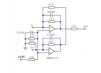
Not too surprising. If much better FFT measurements is your only requirement, the most minimal solution I have seen is Victors's. It requires 2 opamps (schematic attached below), and IIRC, 3 additional 600uf caps in parallel per channel soldered on the underside of the dac board to the bottom side of the existing through-hole AVCC capacitor pins.
On the other hand, if you are interested in improving sound quality in every way audible to a very perceptive human, it takes more than simply minimizing FFT spurs one channel at a time.
Attachments
I've measured quite a bit of ringing on the DSD256 I2S bus signals, when connected only with single wires. It's better to terminate the wires properly using proper signal integrity rules. Finally I've used a normal computer 'flat cable' between AK4137 output and ES9038 input, using 7 wires in G-S-G-S-G-S-G distribution. As these wires usually have approx 100ohm impedance, I've put approx 82 ohm source series resistance on the AK4137 end on the signal wires. This way I could have 'clean' square signals on the ES9038 end.
(If anyone interested in the 'theory' behind, a good source can be found on the following link: https://e2e.ti.com/support/logic/f/151/t/763609 )
Yes, I know and have done all that and written about in the thread before. Problem was that I found non-gold plated pin header connectors increased jitter after sitting overnight, due to slow loss of contact pressure. For awhile I tried soldering ribbon cable directly to boards, but its brittle and doesn't last long if removing and replacing boards frequently for other experiments. For reliability and minimal audible jitter effects I finally used gold plated pins and gold female connectors with small gauge twisted pairs of silver plated teflon wire. I found that some physical separation of pairs seemed to help too. Ultimately, it should probably all go on one board.
All that said, your reminder is good to mention to people now and then. Thank you for that.
I have measured the clock-phase as well (using a chinese RPI-hat AK4137 implementation), IMHO this implementation is according to the specifications.
( DSD data is changing at falling edges of the BCLK, and stable at rising edges )
View attachment 889860
It is programmable in an AK4137 register. For the old AK4137 boards I used that register is set to (IIRC the default of) inverted. Hopefully, the firmware is better for all the different types of boards now. People should have a scope to or logic analyzer to check though.
...NOTE: 25MHz is not mandatory, optimal would be 22.5792MHz clock, but as Mark stated earlier, 25MHz works even fine.
NOTE2: using this single source clocking, the DPLL=1 was also stable.
For best sound quality everything from USB board through AK4137 and dac chip should be clocked synchronously.
EDIT: Accusilicon makes audio frequency clocks available at frequencies up to a bit under 100MHz. They can be divided down for use with AK4137 and USB boards. Costly, but very low jitter too. IMHO, the low jitter is an audible improvement if there aren't other bigger problems in the dac or reproduction system that mask the jitter improvement.
Also, regarding AK4137, its DSD256 sounds better than its DSD128, but it is not specified to both upsample and convert to DSD256 at the same time. It does work, but sound quality suffers in that case. Another thread in this subforum uses two AK4137 in series for a more correct approach. First one upsamples, second one converts to DSD256: Simple DSD SRC for BeagleBone
Last edited:
Hi Markw4,
Thank you for the circuit! Unfortunately I have no spare opamps on the board, just one dual opamp for the both channels. Redesigning the entire analog part…. ? Hmm…. maybe, but wouldn’t it be simpler just to order different DAC boards, not ES9038Q2M based probably. I just need 3 DAC boards for a 3-way digital crossover I’ve been trying to create.
I’m not a perfectionist, at this point at least and need just to move forward, but
I think a – 80db harmonic is too and unacceptably high. Any level below -100db would be acceptable and I still believe ES9038Q2M can do that. There should be something very stupid in the boards, I own some ES9038Q2M devices with much better performance and convinced that -100db is possible. For now I’ve realized (from the experiment) that absence of native I/V conversion is not a reason at all.
I have a couple ideas to verify, I could inform you on the results, if you would like me to. Thanks anyway!
Hi Serge,
ES9038Q2M is quite capable of the performance IVX mentioned in post #6049. IME and IMHO its sound quality can be improved beyond that shown by typical FFT measurements.
Unfortunately for what you want to do, pretty much all cheap Chinese dac boards are going to have a name brand part on them and everything else about them will be done at absolutely rock bottom cost to the manufacturer. That's how they manage to make a profit. It means it should not be unexpected that they can benefit from some better components and better circuitry.
That said, if good off-the-shelf sound quality at low cost is what you want, IME AKM dac chips are easier to make sound good than those made by ESS. The ESS claim to fame is that they make Swiss Army Knife chips with lots of built-in bells and whistles, and they measure well. By comparison, AKM keeps it simple with one chip for one basic function, goes for best sound quality, and 'good enough' in terms of measured specs. Again unfortunately, there was just a bad fire at AKM's foundry and their chips are going to be rare possibly for 6-months or more. If you find AK4493 dacs you like still available, its a fairly good sounding part at lower cost than AK4497 or AK4499.
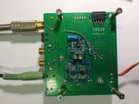
EDIT: Another thing you might consider although there is some work involved, which would be to add one or more SMD opamps to the bottom side of your dac board. The ground plane on the boards we use in this thread is actually a pretty good place to add some circuitry. The first dac I modded in this thread (or ever for that matter) was done that way. See attached pic, for example.
EDIT: If considering building anything, please try to use good passive components: Metal film or thin film resistors, film or NPO ceramic caps if needed in the audio path (50v or 100v NPO are more linear than the 25v ones according to AP guy article), X7R ceramic or possibly film for bypass, etc.
ES9038Q2M is quite capable of the performance IVX mentioned in post #6049. IME and IMHO its sound quality can be improved beyond that shown by typical FFT measurements.
Unfortunately for what you want to do, pretty much all cheap Chinese dac boards are going to have a name brand part on them and everything else about them will be done at absolutely rock bottom cost to the manufacturer. That's how they manage to make a profit. It means it should not be unexpected that they can benefit from some better components and better circuitry.
That said, if good off-the-shelf sound quality at low cost is what you want, IME AKM dac chips are easier to make sound good than those made by ESS. The ESS claim to fame is that they make Swiss Army Knife chips with lots of built-in bells and whistles, and they measure well. By comparison, AKM keeps it simple with one chip for one basic function, goes for best sound quality, and 'good enough' in terms of measured specs. Again unfortunately, there was just a bad fire at AKM's foundry and their chips are going to be rare possibly for 6-months or more. If you find AK4493 dacs you like still available, its a fairly good sounding part at lower cost than AK4497 or AK4499.
EDIT: Another thing you might consider although there is some work involved, which would be to add one or more SMD opamps to the bottom side of your dac board. The ground plane on the boards we use in this thread is actually a pretty good place to add some circuitry. The first dac I modded in this thread (or ever for that matter) was done that way. See attached pic, for example.
EDIT: If considering building anything, please try to use good passive components: Metal film or thin film resistors, film or NPO ceramic caps if needed in the audio path (50v or 100v NPO are more linear than the 25v ones according to AP guy article), X7R ceramic or possibly film for bypass, etc.
Attachments
Last edited:
- Home
- Source & Line
- Digital Line Level
- ES9038Q2M Board