Let's talk for a moment about I2C bus programming. In the program you will see many sections of code that look a lot like an example from the I2C library .md file:
if (!i2c_start((I2C_7BITADDR<<1)|I2C_WRITE)) { // start transfer
Serial.println("I2C device busy");
return;
}
i2c_write(MEMLOC); // send memory address
i2c_rep_start((I2C_7BITADDR<<1)|I2C_READ); // restart for reading
byte val = i2c_read(true); // read one byte and send NAK to terminate
i2c_stop(); // send stop condition
To understand what you are looking at above, i2c_start() is a function that is the first step to communicating with an I2C device. In the above example, that function is embedded in some code that will print an error message if the I2C device you want to communicate with does not respond. Like a phone number, or an address on a house, every device has an address which must be enclosed in the parenthesis after the i2c_start() function. In the above example rather than putting the address number in the parenthesis they put an expression that causes the Arduino to do a little calculation to get the address they want use. In most cases my program keeps it pretty simple and just uses the address number itself.
Now moving along to the next line, it calls a function called i2c_write() which will write an 8-bit number to the I2C device. Since DAC chips generally have registers, the way it normally works with registers is that the first number you write to the dac will be the address number of the register you are interested in reading or writing to. In the above code example they the used a variable called MEMLOC to hold the address of the register, but they could have just written the register number directly.
Before we get to the next line, if we wanted to write data to the register we selected in the last call to i2c_write() we would just call that same function again in the next line but this time we would put the 8-bit data we want written inside the parenthesis. In the above example, they don't want to write data to the register, rather they want to read out the data already in the register. The way it works with I2C bus is that requires a bus operation to be performed called a restart. Thus they call i2c_rep_start() which will change the I2C bus address of the device we want to read. For i2C bus that will be the write address of the device plus one. When a repeat start is used the register number we already selected still stays selected, and the I2C device we are talking to is now prepared to let us read that register.
The next line calls the function byte i2c_read() which reads whatever data is in register and copies into a variable which in this case is called val. Notice the term byte appears before the variable name. That tells the Arduino compiler that the variable val will hold 8-bits of data (the compiler needs to be told the type of variable once for each variable, so they just chose to stick it in the same line as the function call but they didn't have to do it there).
Now we are to the last line of the I2C communication for the moment. Thus we say goodbye and hang up the call with the I2C device by calling the function i2c_stop().
So, all that code was to read one register in one I2C device. Now you know what you are looking at when you see lines of code following that sequence of function calls.
Last edited:
Thank you Mark for your effort to try to learn people like me ")
I will read your post again tomorrow, close to midnight here.
I did some research a few hours back regarding the aurdino due, seems that it’s not supporting eeprom.h. Anyway, i order a Arduino Uno that will arraive monday.
So, sorry, i will have to start over whit my questions again...
BR// Daniel
I will read your post again tomorrow, close to midnight here.
I did some research a few hours back regarding the aurdino due, seems that it’s not supporting eeprom.h. Anyway, i order a Arduino Uno that will arraive monday.
So, sorry, i will have to start over whit my questions again...
BR// Daniel
eeprom.h is not really needed for this. It was a way to store some extra information if there wasn't otherwise enough memory. Please feel free to ask if unsure about anything, or even if considering buying something. Maybe you need it, maybe you don't. Maybe money could be better spent elsewhere. In time, and in part as a result of your experiments here hopefully you will have gained some good experience for the next project down the road.
Last edited:
Some progress on the Uno try.
I did manage to upload your program Mark
I tried, not so smart maybe, without the isolator...
I started the dac with MCU, then power on the Uno. Changed cables from old MCU to the Uno (haven’t got a relay yet, so moved the to cables)
But then i remebered the pullup resistors. With the way i did i now i didn’t have any connected.
But maybe i got some communication anyway?
See pictures. First one i tried to read register 7(don’t know if that one excist), then i send 11 to dac (dpll)..got an answer...
BR // Daniel
Attachments
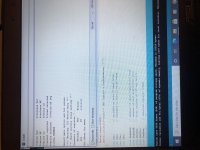
No, actually no communication. The "Warning: I2C Device Busy" message is the clue that the dac didn't respond. The numbers displayed in that case are not useful.
What I would suggest doing to start with is take a look in the I2C library package you downloaded. It contains some sample programs you can load into your Arduino if you edit them a little so it knows which are the correct I2C pins the model of Arduino you have. A particular one that is useful is an I2C bus scanner. It will find the read and write addresses of any I2C devices that respond on your I2C bus. That program is what I used to find the address of my ES9038Q2M dac in the first place. If the current dac design you have now connects the address selection pins on the dac chip differently from how it was done with the older dac boards then you may have to edit my program to change all the dac addresses. Easy to do though. On the other hand if the scanner program doesn't show that the dac chip is responding then you probably have an I2C bus hardware problem or you have misconfigured the program to work with your particular model of Arduino. A scope is quite helpful for observing bus activity so you can know if the hardware of the Arduino and of the bus is good.
What I would suggest doing to start with is take a look in the I2C library package you downloaded. It contains some sample programs you can load into your Arduino if you edit them a little so it knows which are the correct I2C pins the model of Arduino you have. A particular one that is useful is an I2C bus scanner. It will find the read and write addresses of any I2C devices that respond on your I2C bus. That program is what I used to find the address of my ES9038Q2M dac in the first place. If the current dac design you have now connects the address selection pins on the dac chip differently from how it was done with the older dac boards then you may have to edit my program to change all the dac addresses. Easy to do though. On the other hand if the scanner program doesn't show that the dac chip is responding then you probably have an I2C bus hardware problem or you have misconfigured the program to work with your particular model of Arduino. A scope is quite helpful for observing bus activity so you can know if the hardware of the Arduino and of the bus is good.
Did another try.
Maybe i have communication now.
Problem is that i broke my MCU on the Dac card.
Not the hold world, pcb was dammage from soldering anyway, so it was a ”practice card”.
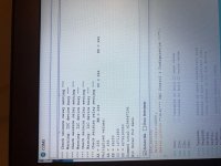
But now i can’t see anything I guess? All register is 0?
BR // Daniel
Maybe i have communication now.
Problem is that i broke my MCU on the Dac card.
Not the hold world, pcb was dammage from soldering anyway, so it was a ”practice card”.
But now i can’t see anything I guess? All register is 0?
BR // Daniel
Attachments
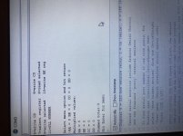
Zeros means the bus SDA line was always low, all ones means its always high. No warning message about I2C device busy means it thinks a device returned an I2C bus ACK in response to its address being written on the bus.
If things are broken, its hard to say exactly what might be displayed. A scope is highly useful for investigating bus issues. Does the bus always hang when a particular device is connected? Are there pullups? Is something shorted to ground on the bus? Is the master device sending SCL clock pulses? Etc.
EDIT: Regarding the MCU on the dac card, you don't need it to operate the dac. However, you would need to enable the dac analog outputs via the appropriate register write before any sound could come out.
Also, if you select a register for general writing/reading and then try to read it, if you get the warning message about I2C device busy, then no bus ACK is being received in response to its address being written on the bus.
EDIT 2: Seeing a zero PLL number could possibly happen if there was no digital input or if ASRC was disabled. Seeing all zeros and no warning message would make me inclined to try some other things to get a better idea of what is going on. Try some other registers, etc. You can also try options that write to C2, C3 registers, you can't hurt anything and it won't write anyway unless you confirm that you really want to.
Last edited:
Okay then, I guess its about time to talk in a general way about numbers, registers, bits, notation, and stuff like that.
First we need to be comfortable working in Hexadecimal (Hex), Decimal, and Binary number formats. Windows comes with a software calculator which has a handy 'Programmer' mode. The three little horizontal lines in the upper left corner of the calculator are where you can click to see a menu of the various modes. In programmer mode it displays numbers in HEX, DEC, OCT (Octal), and BIN formats. When first opened there is a little black rectangle to the left of where DEC format numbers are displayed. The little rectangle can be moved around to select in the data entry format you want to use.
Some basic information on how we write numbers and encode them in columns can be found at: Arabic numerals - Wikipedia
Moving along to the subject of registers, I2C bus is an 8-bit bus which means that most data we will be working with will 8-bits at a time, or 8-bits of data per register address.
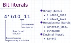
Before getting to some actual dac registers there is some other notation sometimes used for FPGAs and such which may be encountered from time to time. First please see the attachment below describing bit literals. In association with the literals sometimes notation such as [7:5] may be seen. That could be read as, "Starting at Bit-7 and continuing down through Bit-5." Of course, bits are numbered from right to left, with the rightmost bit being bit zero (representing 2 to the 0 power, or 2^0)
Okay, on to dac registers: They typically contain a set of 8 bits. Sometimes the bits can represent a row of switches, some of which may be on (1), and others off (0). Or, some bits might be organized into groups of a few bits that represent a set of possible options only one of which may be selected at a time. There is basically no limit to what a bit or a group of bits might represent. In any case, we can only read and write them in groups of 8 when they are in an 8-bit register.
So, at some point we it would be nice to develop a way to turn on or off any bit we want without disturbing all the other bits in the same register. We can do that in software with a little bit of coding.
Once we are all comfortable with the above topics, we can move on to an example dac, say, one from AKM that we are free to talk about.
First we need to be comfortable working in Hexadecimal (Hex), Decimal, and Binary number formats. Windows comes with a software calculator which has a handy 'Programmer' mode. The three little horizontal lines in the upper left corner of the calculator are where you can click to see a menu of the various modes. In programmer mode it displays numbers in HEX, DEC, OCT (Octal), and BIN formats. When first opened there is a little black rectangle to the left of where DEC format numbers are displayed. The little rectangle can be moved around to select in the data entry format you want to use.
Some basic information on how we write numbers and encode them in columns can be found at: Arabic numerals - Wikipedia
Moving along to the subject of registers, I2C bus is an 8-bit bus which means that most data we will be working with will 8-bits at a time, or 8-bits of data per register address.
Before getting to some actual dac registers there is some other notation sometimes used for FPGAs and such which may be encountered from time to time. First please see the attachment below describing bit literals. In association with the literals sometimes notation such as [7:5] may be seen. That could be read as, "Starting at Bit-7 and continuing down through Bit-5." Of course, bits are numbered from right to left, with the rightmost bit being bit zero (representing 2 to the 0 power, or 2^0)
Okay, on to dac registers: They typically contain a set of 8 bits. Sometimes the bits can represent a row of switches, some of which may be on (1), and others off (0). Or, some bits might be organized into groups of a few bits that represent a set of possible options only one of which may be selected at a time. There is basically no limit to what a bit or a group of bits might represent. In any case, we can only read and write them in groups of 8 when they are in an 8-bit register.
So, at some point we it would be nice to develop a way to turn on or off any bit we want without disturbing all the other bits in the same register. We can do that in software with a little bit of coding.
Once we are all comfortable with the above topics, we can move on to an example dac, say, one from AKM that we are free to talk about.
Attachments
Last edited:
One thing I forgot to mention about the Bit Literal attachment above: The symbol (letter) x can be used to indicate that a bit, or a group of bits, is in an unknown state, and the symbol (letter) z can be used to indicate a physical binary signal, or a group of them, is in a high impedance, or floating state. The x and or z bit literal symbols might be seen when working with FPGAs, but probably not very likely to see them used in association with dac registers.
EDIT: Another good resource on HEX notation: Hexadecimal - Wikipedia
EDIT: Another good resource on HEX notation: Hexadecimal - Wikipedia
Last edited:
I am going to buy a (-15V)-0V-(+15V) trafo for the es9038q2m board. I already have built the 5V DC power source. What is the best choice for the (+15)-0-(-15) trafo? (toroidial or r-core)?
I was thinking I will go for at least 30V*A because I have always heard good results when using a power source with higher current capacity than required for DACs.
Is toroid or r-core recommended?
If toroid is recommended,
-I see YHDC, BingZi and talema available.
-Is there one brand which is known to be reliable or the best out of those brands?
Or should I go for r-core?
-The r-core trafos I see are made of "Japan steel coiled silicon steel sheet".
Thanks a lot everyone,
-Philip
Last edited:
Looking for a design for the +-15V PSU.
I just got done going through this thread to find (+15V) 0V (-15V) power supply suggestions.
Since I already have a +5V DC psu, my (+15V) 0V (-15V) psu will use its own separate transformer.
I want to spend no more than ~$50 total for the 15v psu circuit, including the trafo. Should I use an opamp circuit? Is a 1A trafo okay if I do? Should I use (+15V) 0V (-15V) or something further from zero on each side? Can anyone recommend a design for the circuit or PSU? I want something good and trusted for <~$50 total,
That will be my last part to build in order to get my DAC working.
Thanks a lot,
Philip.
Philip,
I recommend to use an R-core with two separate 18v (or maybe 15v) windings and two separate 9v windings (no center-tapped windings).
Also, for +-15v (or +-11v) supplies I recommend dual LT1083 power supplies like these: LT1083 Adjustable HIFI Linear Regulated Power Supply Board Dual Output | eBay
...Since LT1083 is a positive regulator only and because the two regulators on the above power supply boards do not share a common ground, I can use one regulator sort of upside down to regulate the -15v rail too. In that case the + output goes to ground on dac board, and the - output goes to the -15v rail on the dac board. I run a separate ground wire from each regulator to the dac board.
For a separate 5v (or 3.3v) supply I have been using an LT3042 board like: Low Noise LT3042 Linear Regulator Power Supply Board DC Converter Overvoltage | eBay ...Or, like: Dual Output LT3042 Ultra-Low Noise Linear Regulated Power Supply | eBay ...The regulator output voltages are set with a small SMD resistor. The seller normally can provide the output voltage you need, or you can change it later by changing the resistor.
The 5v supplies run from the 9v transformer windings.
Last edited:
Daniel,
You can ask questions at any time, but when we get to same examples then things will start to get more clear very quickly. The point of most of the stuff I wrote about numbers was to help get you comfortable that there are different ways to write down the same number. For example, if I have 12 marbles it doesn't matter if I write it down in Roman Numerals or Hex, or whatever notation system. Its still 12 marbles.
The notation systems we most often use with computers are Bin and Hex (Base 2, and Base 16). We do that simply because it turns out to be very convenient when we are working with computer and dac registers.
Even if Arabian positional notation we use with everyday Base 10 numbers has an abstract theory that we can apply to other number bases, the Windows Programmer mode calculator makes it easy to ignore the theory if we want and we can just go ahead to program a dac as we wish.
The other thing is that a row of bits like 00110101 is just a row of bits. We can interpret it as expressing a numerical value, or we might choose to think of it as the on/off pattern of a row of switches, or whatever else we want. It can be be any or all of the above things if we want to think that's what it represents. Its just that when we manipulate it in a computer its often more convenient to think of it as number and when we look a dac data sheet it may sometimes be more convenient to think of it in other ways instead. Again, when we get to an example dac it should start making a lot of sense.
Last edited:
Hi Mark,
Okay great, I just ordered one of the dual lt1083 power supplies.
For the 18v trafo, that is (-18V)(+18V) not (-18V)(0V)(+18V)
I already have a 5V DC power supply with the regulator you suggested so I will use that if it will work fine, and buy a separate 18V trafo for the 15V PSU.
I will send you a message with the 18V trafo I find in a minute just to make sure I picked one that will work alright...
Thanks a lot,
Philip
- Home
- Source & Line
- Digital Line Level
- ES9038Q2M Board