352.8 in both cases of course.
HQP was at -2db and the DAC digital attenuator is used to control volume, it was never higher than about -10db
Probably better to attenuate the digital signal coming into the dac by about 3dB in order to minimize distortion. Many dacs produce lower measured distortion if operated at peak levels somewhat below 0dBFS, some as low as -10 or -12. For AK4499 -3dBFS appears to be about right.
Best volume control after that is probably a high quality dual ganged pot on the analog outputs somewhere after the I/V stage or differential summing stages. That turns down the noise floor at the same time as the music.
Anyway, IIUC now, physically speaking you basically ran the dac at 24/384 and changed the dac filters, and you found that the slowest filter sounded by far the best under the conditions of the testing? Am I still not clear on anything? Sorry, just want to be sure I understand.
Last edited:
Hi Mark
Firstly thank you for your big effort in to this thread it must be a hobby for you also��
Yes i would be pleased to see the link to your though hole version.
I am thinking buying this Dac for playing, do you think it is possible to split avcc power supply to this board?
I dot not know if I the version with display/ encoder yet??
Best regards
ES9038 Q2M DAC DSD Decoder Support IIS DSD 384KHz Coaxial Fiber DOP | eBay
Does anyone know if there is a schematic for the listed 9038q2m?
Thanks
Does anyone know if there is a schematic for the listed 9038q2m?
Hi,
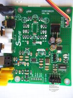
Never saw a complete schematic for it, but its never been a problem. We could probably draw one up if anyone was motivated enough.
Basically, the PCB is double sided so its easy to trace out the interconnections. I've probably traced out every part of it at one time or another, but usually we only care about one small area at a time.
One thing we do have is a marked up pic of the board with annotations describing items of possible interest. It is attached below. To see it at full resolution so the text can be read, first click on the image to open it, then while it is open mouse down to the lower left corner and click on the white X symbol. That opens the pic at full resolution. You can also right clock and select to download any image.
Attachments
Laserscrape,
Sorry, man. I didn't mean to give you a bad time. I just never heard of the slowest filter built into the dac referred to as NOS mode. I did read about super slow before when going through the data sheet, but it didn't occur to me that I would have any use for it so it kind of got put to the side in my mind. Never bothered to look for/at a frequency response graph either.
In general my experience with dac filters at different stages of implementation is that which filter sounds best changes depending on what problems are left to fix in the dac. Therefore, I tend to ignore the filter choices and use the default one until I get the dac sounding as good as I can get it. Then it usually turns out the default filter sounds fine, and actually best.
Anyway, I'm still interested in hearing about what you did and hearing more about your diy AK4499 project. Too bad nobody wants to share more details of what they are doing with AK4499. Maybe the time will come when I will dump a bunch of info all at once, but so far most of my AK4499 findings reported in the forum are spread around the in different threads.
Mark
Probably better to attenuate the digital signal coming into the dac by about 3dB in order to minimize distortion. Many dacs produce lower measured distortion if operated at peak levels somewhat below 0dBFS, some as low as -10 or -12. For AK4499 -3dBFS appears to be about right.
Any findings about this behaviour regarding the ESS chips?
You can start reading here:
Is the volume control on DACs usable? | Audio Science Review (ASR) Forum
I am using my es9018 Dac with -15dB volume because high output to my zapfilter 2.
Else I would also like to see measurements proven wrong
Is the volume control on DACs usable? | Audio Science Review (ASR) Forum
I am using my es9018 Dac with -15dB volume because high output to my zapfilter 2.
Else I would also like to see measurements proven wrong
Hi,
Never saw a complete schematic for it, but its never been a problem. We could probably draw one up if anyone was motivated enough.
Basically, the PCB is double sided so its easy to trace out the interconnections. I've probably traced out every part of it at one time or another, but usually we only care about one small area at a time.
One thing we do have is a marked up pic of the board with annotations describing items of possible interest. It is attached below. To see it at full resolution so the text can be read, first click on the image to open it, then while it is open mouse down to the lower left corner and click on the white X symbol. That opens the pic at full resolution. You can also right clock and select to download any image.
Thanks Mark, I have one on its way and wondered if a schematic may have been created at some point. it wont be a problem to trace this out myself.
ta
No problem.
Many people have refered to it as a ''NOS-like'' mode, implying it could just be very gentle filter but seeingwhat it looks like on a scope (not my image btw) I thought it was truly NOS.
Many people have refered to it as a ''NOS-like'' mode, implying it could just be very gentle filter but seeingwhat it looks like on a scope (not my image btw) I thought it was truly NOS.
Any findings about this behaviour regarding the ESS chips?
I did most of my ES9038Q2M testing with AK4137 in the loop. Both ASRCs (the dac chip has one too) may produce intersample overs as a result of resamplinig. Therefore, my results might not apply to the dac chip alone. I found best sound quality was with the digital level leaving the computer at about -8dBFS. Maybe slightly less.
The general tendency in dacs was reported by forum member Audio1 (Demian Martin) in the BT or the BH thread. Since he is an industry expert and a paid consultant for some big audio companies I would expect him to know. I only thought it interesting because what he said matched up with my more limited observations. Also, I sure he would measure whereas I would listen. If we both form the same conclusions then probably something to it. He did not give numbers for any specific dac chips, so can't help you there.
I am using my es9018 Dac with -15dB volume because high output to my zapfilter 2.
I was only talking about dac chips in isolation, the dac chip itself. Once you combine it with another device then what is optimal for the particular combination may be something different than what is optimal for one device alone.
In particular, I looked at the zapfilter website. Sorry, looks like BS to me. Any device represented to work as a universal ideal output stage for any dac is snake oil in my book. Some people may like that sort of thing for the sound effects or whatever. Not something I would use or advise others to use.
Last edited:
Many people have refered to it as a ''NOS-like'' mode, implying it could just be very gentle filter but seeingwhat it looks like on a scope (not my image btw) I thought it was truly NOS.
I agree it does look somewhat NOS-like though with more noise - the steps are at ~22uS intervals by my eye. It would be interesting to see what it does with an 18kHz sinewave.
Quote: If you would be happy with a nice little 16-bit dac for cheap, I would suggest you go check out Abraxalito's thread and see how that appeals to you. Much lower cost for some diy fun and good value for money.
Hi Mark
Have you listen to it and if so how would you describe the difference vs your 4499 eval board, for 16 bit recordings of course? And vs say a more common 4493 or 9038 implementation?
Just curious because you mentioned it
Many thanks
Claude
Hi Mark
Have you listen to it and if so how would you describe the difference vs your 4499 eval board, for 16 bit recordings of course? And vs say a more common 4493 or 9038 implementation?
Just curious because you mentioned it
Many thanks
Claude
Hi Claude, I have one of Abraxalito's earlier dac designs, IIRC, based on the same chip he is still using. At the time I auditioned it I was impressed that the low level reverb tails were more present than they are with much more expensive and complex Sabre dac designs. In other ways it didn't beat out the sound of dacs like Benchmark DAC-3, but the price difference is huge.
Also, I used a spare USB board to provide I2S input and clocking. No comparisons were done with much lower phase noise clocks, so don't know first hand what the jitter sensitivity might have been. In addition, Abraxalito (Richard) sent the dac with output transformers attached so that's how we listened to it. I did hear some low level distortion but I am very sensitive to distortion, don't know if other people would notice. Also don't know if different clocking and or not using the output transformers might have changed the sound significantly. Did find that lower power supply impedance as seen by the dac chip helped it sound better. I believe the newer dacs may have taken that more into account. In the end its still a 16-bit dac, though, and no DSD. Probably best to ask other people how the newer ones with more dac chips and or with more output filtering sound, haven't had the pleasure myself as yet.
Regarding the AK4499 eval board, it can sound a lot like Topping D90 if the same clocks are used. It can sound better than D90 or worse than D90 depending on implementation details. I would say D90 sounds clearly better than DAC-3 at 16/44 (and DAC-3 is upsampling that to 211kHz internally), and probably significantly better than what I remember of the older Abraxalito dac here. So, I would opine the gap between good low cost dacs and dacs of significantly better sound quality is shrinking, but we are still talking several times the cost for D90.
Last edited:
Yes lt3042 Also good example.
What about this small lt3045 module
Could it be a okay upgrade to Chinese Dac?
Sigma78-79 Series LDO Low Noise Linear Regulated Power Supply Module L18-52 | eBay
Happy building
What about this small lt3045 module
Could it be a okay upgrade to Chinese Dac?
Sigma78-79 Series LDO Low Noise Linear Regulated Power Supply Module L18-52 | eBay
Happy building
LT3042 or LT3045 are devices that should work as a good voltage reference. The idea is that the voltage reference should be ultra low noise to be consistent with a good 24-bit dac (maybe 20 or 21 ENOB in reality). If one can't start out with a low noise reference then multiple stages of filtering may be another way to reduce noise.
The forgoing haven been said, cheap $1.99 Chinese voltage regulators are probably not ultra low noise (they claim the one linked to uses Ti-TPS7A 4701RGW, not as good as we would prefer, maybe with enough post-filtering though). TI does have a similar, but ultra low noise version in TPS7A33 family, although not as good at LTC6655 or LT3042.
Perhaps some informative discussion at: Ultra low noise voltage reference - Page 1
Last edited:
Thanks Mark, I have one on its way and wondered if a schematic may have been created at some point. it wont be a problem to trace this out myself.
You know, I’m surprised that in the 2.5 years or so of the life it this thread that the original manufacturer hasn’t picked up these changes. Or some other low cost manufacturer.
Maybe it’s too much to process; it was for me, so I decided to buy Schiit instead of ****. {please interpret as humor not derision}{the asterisks are from diyaudio not me}
Last edited:
LT3042 or LT3045 are devices that should work as a good voltage reference. The idea is that the voltage reference should be ultra low noise to be consistent with a good 24-bit dac (maybe 20 or 21 ENOB in reality). If one can't start out with a low noise reference then multiple stages of filtering may be another way to reduce noise.
The forgoing haven been said, cheap $1.99 Chinese voltage regulators are probably not ultra low noise (they claim the one linked to uses Ti-TPS7A 4701RGW, not as good as we would prefer, maybe with enough post-filtering though). TI does have a similar, but ultra low noise version in TPS7A33 family, although not as good at LTC6655 or LT3042.
Perhaps some informative discussion at: Ultra low noise voltage reference - Page 1
I would suggest to try 2 red LED's in series powered with a 3 to 10 mA CCS.
The CCS can be made with a J111 (etc) jfet and a single resistor.
This will have lower noise than any of these regs or voltage references.
It won't have the temperature vs voltage stability of the aforementioned
references but that isn't important in this case.
Another option is a simple VBE multiplier using low noise BJT such as a
2SA1083/4/5 or equiv. and same CCS. Not perfect voltage vs temp stability,
but super low noise.
TCD
- Home
- Source & Line
- Digital Line Level
- ES9038Q2M Board