https://www.diyaudio.com/forums/dig...facing-amanero-cronus-ak4137.html#post6232871
managed to post a few pics and words of what I did.
managed to post a few pics and words of what I did.
I finally got SRC pcm upsampling to 384kHz to work in Linux Mint! It really had a profound impact on the sound from Youtube. I had to type in; sudo xed /etc/pulse/daemon.conf to access the settings. I changed default sample format to float32ne and default resample method to src-sinc-best quality and default sampling rate to 384kHz. As an alternative it didn't seem to take. I also increased realtime-scheduling/ priority to higher values to help with jitter. Anyone else tried this and compared this method to a physical rescaler board? To me it seems to affect the tweeter phase as the stereo image widened and got more holographic. The upsampling method also got rid of some harsness in the treble, it sounded more like vinyl but not rolled off. More musical somehow and perhaps slightly more laid back. The noisefloor and dynamics are simply stunning. Even at 192kHz the sound change were quite noticable. I also swapped the dual opamps(I run differential signal into the amps without going into SE with opamps) and this opamp is the best by a good margin for me OPA1622 DIP8 High Current Output Low Distortion Dual Op Operational Amplifier | eBay I've tried them in friend's tpa3255 china amp and I got the same improvement and sound signature with that amp also, I'm pretty sure at this point opamps aren't created equal.
Last edited:
Hi impulse60,
Good to hear you are making some progress with software upsampling. Don't know/recall if you have hacked dac I2C registers yet to be able set DPLL bandwidth? If not, it can make a considerable improvement in sound quality to set it as low as you can get it work stably. That's what ESS recommends to do.
Good to hear you are making some progress with software upsampling. Don't know/recall if you have hacked dac I2C registers yet to be able set DPLL bandwidth? If not, it can make a considerable improvement in sound quality to set it as low as you can get it work stably. That's what ESS recommends to do.
Is there a thread on how to get started?
Not really, information is scattered around. If you already have an Ardurino or other MCU, you can probably use what you have. The process of taking control of dac registers is divided into two parts, I2C bus hardware interfacing, and then software coding. Any preferences you have for an MCU?
I tried Arduino some years ago but my coding skills are long gone. I think i'll rather focus triamping with nanodsp next winter. I run my 3 subs already with a dsp and I'm very happy with the results. Have you compared software upscaling into I2S vs those upsamplings boards Mark?
I tried Arduino some years ago but my coding skills are long gone.
I could probably help you quite a bit with that. I have sample code you could start out with. However, up to you if you want to go there. The payoff in sound quality is can be quite qood depending on how low you are able to get DPLL Bandwidth to go. That in turn depends on much jitter coming into the dac inputs. Lower incoming jitter = lower DPLL Bandwidth possible.
Have you compared software upscaling into I2S vs those upsamplings boards Mark?
Of course. Mostly in HQ Player and Roon. I have also learned about the limitations and sensitivities of the hardware upsampling chips. Not sure which path is best in an absolute sense, but software is certainly more versatile with lots of different algorithms available to try. Also, free software is available which makes an attractive option if one already has a computer to use for audio.
Looks like this thread may well end up being the last of the newest DACs to work and mod.
Anything newer at this point appears much pricier relative to the potential performance unless someone comes up with a great implementation that is mod friendly with the AKM4497. The AKM4499 is in a whole different league in terms of costs.
Nothing otherwise happening these days.
Anything newer at this point appears much pricier relative to the potential performance unless someone comes up with a great implementation that is mod friendly with the AKM4497. The AKM4499 is in a whole different league in terms of costs.
Nothing otherwise happening these days.
Hi Mike,
I dunno about AK4499 being too expensive to diy. Maybe though.
Problems to be solved include finishing an engineering design for one that sounds better than Topping D90 without costing way more to build. Also, there are issues soldering some ICs for some diy'ers. May need to have the PCB manufacturer place and solder some of the components, or something like that.
Regarding cost, it probably wouldn't be on the cheap side to build but then some people have a lot invested in TP dacs and or Ian dacs, etc.
To avoid having to do a lot of possibly unnecessary design and test work and also to possibly speed things up, it would be interesting to know how the Japanese DIY AK4499 project board that George has pointed out sounds compared to (a fully warmed up) D90. Until we know more its hard to say if that design might be the most direct path for a hobby AK4499 dac builder.
EDIT: One more thought: AK4498/AK4191 evaluation boards should start becoming available before too long (although mass production of chips is expected to be another year away). No point designing a new really good basic AK4499 PCB for diy project use if AK4498/AK4191 is going to obsolete all that hard work. We probably should see how that combo sounds before putting too much effort into an AK4499 project.
Last edited:
Hi Mark
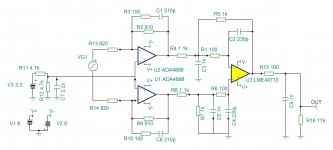
I am thinking building your circuit from post 2573 with three LME49720.
If I start with my ES9018 Dac do you also have recommendation for component values then?
Do you have new values or modificatins since 2018?
Are tantalum great for audio power supply decoupling or could you use nichicon KZ instead for example?
All the best
Last edited:
Hi kimschips,
You could do that, or there is newer version of it and maybe a B.O.M. attached to post #3003 of this thread. In addition, there is a version someone posted of Topping D10 output stage which I will attach below. You can see they are all essentially the same topology, which is a good one (but with some different component values used which we could discuss in more detail).
Of course, a schematic is not the only consideration. Proper components and a good layout matter a lot too. In more recent times I have changed my preferred I/V opamp to OPA1612, although LME49720 can work too. Capacitors in the signal path should be COG or NPO types, and the resistors should be thin film SMD or metal film through hole types.
You may be interested to know I created a through hole component output stage board how-to together with pics and instructions at the request of some thread members. I can give you a link if you would like to take a look at it. However, my preference has always been to go with SMD which I personally find easier to work with. The guys wanted through hole parts though, so that's the version I did.
Regarding differences between ES9038Q2M and ES9018, the only thing that matters from output stage perspective is dac maximum output current. The I/V feedback resistor value can be adjusted to give the output voltage swing needed (usually configured for about 3v peak to peak maximum output swing).
Also, something I found out recently with AK4499 is that the I/V and other output stage opamps may sound better running from +-11v power rails instead of using the more typical +-15v. Don't know why, but it works with AK4499, so probably worth a try with ESS dacs too.
Please let me know if you have any more questions or would like to discuss further.
Attachments
Last edited:
Hi Mark
Firstly thank you for your big effort in to this thread it must be a hobby for you also��
Yes i would be pleased to see the link to your though hole version.
I am thinking buying this Dac for playing, do you think it is possible to split avcc power supply to this board?
I dot not know if I the version with display/ encoder yet??
Best regards
ES9038 Q2M DAC DSD Decoder Support IIS DSD 384KHz Coaxial Fiber DOP | eBay
Last edited:
That one doesn't appear to have a display or encoder. Regarding splitting AVCC, it already is split on that one (its the same board mostly used for modding in this thread). However, I kind of have to warn you I think that jumping in and buying a new board like that at this point might not be as good an idea as one might imagine. After we did a lot of modding of those boards in this thread we found it takes a lot of work and also some added money to turn one of those into a much better sounding dac. Most people never made it all the way to the end. Maybe they got tired of modding dacs and or decided theirs sounded good enough at some point to be happy with. Don't know. Do know I would not mod a Sabre dac again myself, been there done that, type of thing. Better dac chips are out now and more will be coming out pretty soon, so many of us have decided its best to move on. Of course, doesn't mean that's the right choice for everyone. Some people are still finding new ways to keep getting a little bit more sound quality out of ES9038Q2M, but most of those advances are not things we fully worked out in this thread. We know something about them, but not at a cookbook level.
Link to the output stage project is: Dropbox - Output Stage Instructions.zip - Simplify your life
Link to the output stage project is: Dropbox - Output Stage Instructions.zip - Simplify your life
The file opens using Wordpad for me, although there is a slight processing delay at the start. Also, Windows asks me if I want to open it with unsecure content or with secure content only. Don't know why, it only has text and pictures inside. Also, content looks the same to me whichever way I open it, blocked or unblocked. The file was created with Open Office. If you can confirm that Wordpad doesn't know how to open it on your PC then I can try another format, but not sure if it will help.
kimschips,
Maybe it would help if you would tell me what you tried so far: Do you have a Windows PC? If so did you download and extract the .zip file to a folder on your local computer? If so, what programs did you use to try to open the RTF file? If it didn't open did you get any error messages, and if so what did they say?
Maybe it would help if you would tell me what you tried so far: Do you have a Windows PC? If so did you download and extract the .zip file to a folder on your local computer? If so, what programs did you use to try to open the RTF file? If it didn't open did you get any error messages, and if so what did they say?
Hi kimschips,
You could do that, or there is newer version of it and maybe a B.O.M. attached to post #3003 of this thread. In addition, there is a version someone posted of Topping D10 output stage which I will attach below. You can see they are all essentially the same topology, which is a good one (but with some different component values used which we could discuss in more detail).
Of course, a schematic is not the only consideration. Proper components and a good layout matter a lot too. In more recent times I have changed my preferred I/V opamp to OPA1612, although LME49720 can work too. Capacitors in the signal path should be COG or NPO types, and the resistors should be thin film SMD or metal film through hole types.
You may be interested to know I created a through hole component output stage board how-to together with pics and instructions at the request of some thread members. I can give you a link if you would like to take a look at it. However, my preference has always been to go with SMD which I personally find easier to work with. The guys wanted through hole parts though, so that's the version I did.
Regarding differences between ES9038Q2M and ES9018, the only thing that matters from output stage perspective is dac maximum output current. The I/V feedback resistor value can be adjusted to give the output voltage swing needed (usually configured for about 3v peak to peak maximum output swing).
Also, something I found out recently with AK4499 is that the I/V and other output stage opamps may sound better running from +-11v power rails instead of using the more typical +-15v. Don't know why, but it works with AK4499, so probably worth a try with ESS dacs too.
Please let me know if you have any more questions or would like to discuss further.
WRT 11V vs 15V PS rails, that is surprising. Normally the opposite is the case and they nearly always measure slightly better with higher rails.
WRT the I-V schematic, have you checked what LPF function it is or if it is 'linear phase'? There have been plenty of published I-V LPF's that didn't have
linear phase response which is a no-no.
WRT NPO ceramic caps, they do measure very low distortion but I've nearly
always used Wima FKP (Film+Foil polyprop) caps for LPF circuits.
TCD
- Home
- Source & Line
- Digital Line Level
- ES9038Q2M Board