44.1khz input now shows 48khz on Dac display. But 48khz input shows right number 48khz. Any explanation?
Just to clarify, which version of board and display do you have?
In regard to your question, the incoming audio sample rate can be estimated from the 32-bit DPLL number registers. Some hint about a possible relationship can be found in the data sheet NCO Number register information. Basically, the MCU has to know the MCLK frequency in order to estimate the frame rate from the DPLL number. It may also be necessary to know the word length, since that gives the relationship between BCLK and LRCK. Presumably the DPLL might actually track the faster BCLK, but some testing would need to be done to verify if so.
Anyway, if the MCU is expecting a 100MHz clock and 80MHz is being used instead, then DPLL Number would need to be interpreted differently to best estimate the frame sample rate.
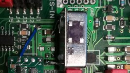
Thank you Mark, i thought similar but was not sure because past modifiers that swapped ordinary clocks to NDK but probbably in designs with no sample rate indicator.
I installed back 100mhz clock ...blah... couldn*t hear to music anymore. Sharp, harsh, light sounded... i luckily found one tcxo from audiogd but big size and installed it...very similar to ndk. It will stay inside for now. This dac is just for playing in this times that all world is stopped to do business.
Now sound has similar fuller character as Ian stack with dual es9038q2m.
Attachments
Anyone got some recent pictures of their progress?
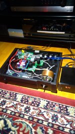
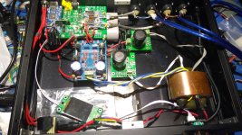
I finally got mine to work with no distortions or problems") . It sounds holografic compared to my previous dac and the sound signature matches my speakers very well. The new R-transformer didn't come with a shield so I added a copper shield around it. I don't know if it makes any difference though^^. I also skipped star ground since there is very few ground loops because of the multiple psus and it didn't prevent hum in the previous configuration. The new R-transformer goes into dual Lt3042 5v into Lt3042 3.3v/liFe and into AVCC. The +-15V ac line goes into Walt Jung regulator and into opamps. I still got slight hum but I think that is the temporary xlr to unbalenced connection(without summing opamps).
. It sounds holografic compared to my previous dac and the sound signature matches my speakers very well. The new R-transformer didn't come with a shield so I added a copper shield around it. I don't know if it makes any difference though^^. I also skipped star ground since there is very few ground loops because of the multiple psus and it didn't prevent hum in the previous configuration. The new R-transformer goes into dual Lt3042 5v into Lt3042 3.3v/liFe and into AVCC. The +-15V ac line goes into Walt Jung regulator and into opamps. I still got slight hum but I think that is the temporary xlr to unbalenced connection(without summing opamps).
I still haven't got the new amp complete, so I had to jerry rig something into the old amplifier, so disregard the blue rca cable.. The housing for the screen also need some coats of paints before I can complete the build.
I measured the LiFePo4 batteries today and they had only dropped 0.05V on two weeks. They are permanently connected to the AVCC, and standby discharge doesn't seem to be a problem.
I finally got mine to work with no distortions or problems
. It sounds holografic compared to my previous dac and the sound signature matches my speakers very well. The new R-transformer didn't come with a shield so I added a copper shield around it. I don't know if it makes any difference though^^. I also skipped star ground since there is very few ground loops because of the multiple psus and it didn't prevent hum in the previous configuration. The new R-transformer goes into dual Lt3042 5v into Lt3042 3.3v/liFe and into AVCC. The +-15V ac line goes into Walt Jung regulator and into opamps. I still got slight hum but I think that is the temporary xlr to unbalenced connection(without summing opamps).I still haven't got the new amp complete, so I had to jerry rig something into the old amplifier, so disregard the blue rca cable.. The housing for the screen also need some coats of paints before I can complete the build.
I measured the LiFePo4 batteries today and they had only dropped 0.05V on two weeks. They are permanently connected to the AVCC, and standby discharge doesn't seem to be a problem.
Attachments
impuls60,
Good to hear you have the dac performing to your satisfaction.
If you are like many of us, we will probably be spending more time at home, and perhaps in need of something to keep mentally occupied. Would you say there is more in the way of diy projects to come?
Good to hear you have the dac performing to your satisfaction.
If you are like many of us, we will probably be spending more time at home, and perhaps in need of something to keep mentally occupied. Would you say there is more in the way of diy projects to come?
Absolutely Mark! Having my audio projects to focus on while beeing Corona stuck have been a good timepass Been testing my system on Andre Rieu's dvds which has been released on Youtube the last days! I find the sound from this dac to work very well with live sound, one can far into the audience or orchestra.
I am also soon to complete a diy amp with twin 3e audio 3255s with a huge linear powersupply. Can't wait to test out the complete system in balanced mode.
Been testing my system on Andre Rieu's dvds which has been released on Youtube the last days! I find the sound from this dac to work very well with live sound, one can far into the audience or orchestra.I am also soon to complete a diy amp with twin 3e audio 3255s with a huge linear powersupply. Can't wait to test out the complete system in balanced mode.
I am also soon to complete a diy amp with twin 3e audio 3255s with a huge linear powersupply. Can't wait to test out the complete system in balanced mode.
Me too!
525VA 35v.....trying both monolithic and also an ideal bridge.
Sorry for OT
Stay healthy
Attachments
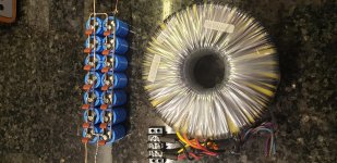
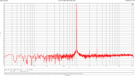
The result is VERY clean
Sure. Did you by chance try listening to the difference between an ultra low phase noise (@10Hz offset and below) clock module verses the low cost crystal? Just wondering
to me, there is no difference in the sound at all. But I'll not argue if someone believes he can hear that.
The people in this thread who started modding ES9038Q2M boards noticed that dac sound kept improving more and more with each mod. And the mods all make sense from an engineering perspective. There is no way starting with the the things that ESS recommends doing should make dacs sound less accurate, and it doesn't. It makes ESS dacs sound more accurate.
However, I have seen some dac implementations with many things done in a way so as to obscure hearing much improvement until a minimal number of issues have been addressed. Seems likely many of the people who have modded dacs have some idea of what I'm talking about.
Are they all using the same evaluation process and what is that process?The people in this thread who started modding ES9038Q2M boards noticed that dac sound kept improving more and more with each mod.
Accurate to what?There is no way starting with the the things that ESS recommends doing should make dacs sound less accurate, and it doesn't. It makes ESS dacs sound more accurate.
For me the clapping of audiences let go the speakers and made the clapping continue between the speakers. The individual claps were also much more defined, so more realistic. Depth and scale also improved. In many systems one can hear some clapping, but not get a feel for the size of the audience. Another example is that I can single out instruments easier after the mods.
Even though we all have different everything(ears, equipment and room), some mutual traits have appeared from mods here in this thread. That's motivation enough for me to keep changing things
Even though we all have different everything(ears, equipment and room), some mutual traits have appeared from mods here in this thread. That's motivation enough for me to keep changing things
No need to bother trying ES9311 for ES9038Q2M, since the dac's AVCC current demand is very low. An opamp buffer works fine, and is time proven.
Regarding ES9311 for the ESS PRO chips, Acko dac tried it and said it didn't sound much different from the ADM715x part they use instead. Now, using ADM7150 for AVCC is something I do have some experience with and have written about. My recommendation is to stick with the opamp buffer circuit for ES9038Q2M, it sounds better.
Regarding ES9311 for the ESS PRO chips, Acko dac tried it and said it didn't sound much different from the ADM715x part they use instead. Now, using ADM7150 for AVCC is something I do have some experience with and have written about. My recommendation is to stick with the opamp buffer circuit for ES9038Q2M, it sounds better.
I’ve just substituted the low noise version of the ltc6655 (ltc6655ln2.5) in the avcc supply circuit. It requires one extra 10uF cap and because it’s 2.5v output t you also need a couple of resistors around the opamp to get 3.3v out. I feel sound quality has improved with even more clarity.
Hi Tim,
Good to hear you are happy with the change. Hope it will be okay if I ask a few of questions:
What were you using as a refereence before the LTC6655?
Was there some reason for using the 2.5v version rather than the 3.3v version?
Which opamps are you using?
The dac should still work with AVCC at 2.5v, so I would suggest to take careful note of how it sounds (aside from maximum volume level) before changing anything else such as opamp gain. Then check sound quality again after the change. Reason for the suggestion is that its not clear if anyone here has experimented with that before.
If you do decide to do before and after listening tests, maybe a good idea to listen at more than one volume level to see how volume level affects sound (in addition to the expected Fletcher-Munsen effect). Otherwise, if using fixed volume listening comparison then this would probably be one of those cases where level matching of before and after listening tests would make a lot of sense. Use the same music for both listening tests too. It will be interesting to see what you find out
Last edited:
Hi. I was using the standard ltc6655 at 3.3v. At the moment the LN version is only available at 2.5v hence the resistors. Opamps are OPA1612. I’ll have a go at 2.5v and see how it sounds. I tend to have two volumes I use - wife around and wife not around (wife is younger than me and has better hearing) Currently my wife is shirking from home so max volume limited. I could go quiet and very quiet I suppose
...tend to have two volumes I use...
Another option might be to pick up some gain in a later stage. It could be done in I/V or maybe in a preamp. One downside is that signal to noise ratio would probably be a little better with 3.3v.
However, this is audio: The only way to know what a circuit really sounds like is to build it then listen (always including the power supply when thinking about what constitutes the circuit).
BTW, a really surprisingly good power supply can be found in the thread that reversed engineered the Pass Labs HPA-1 (a Jam Somasundram design): Pass HPA-1, what do we know? ...schematics and gerbers if one looks around enough. (Gerbers may have ended up in another thread, don't recall).
- Home
- Source & Line
- Digital Line Level
- ES9038Q2M Board