Looks like someone snatched up the last AK4499 eval board at Digikey. No more expected until November, they say.
Could be a dedicated AK4499 thread may not be needed for some time at this rate.
Happily, it turns out AKM has done a pretty effective job of making AK4499 eval board sound good out of the box using only +-15v, +5v, and +3.3v external power supplies along with one's choice of USB board and clocks.
Also turns out that some of the eval board design seems likely worth a try with Sabre DACs. Could help make it easier to get them sounding their best, even though they will still have some of that ESS dac sound. Here, I am thinking of the Reference Voltage (similar in function to AVCC) design starting with Jung type regulators, one per channel, and including some 10-ohm resistors and electrolytic caps at the dac. Interesting how that seems to work to shape the sound. However, might be more likely to work with stereo-only configurations given how Sabre AVCC is divided up into channels.
Last edited:
Jung uses the output of the regulator to drive the error correction op amp.
That means that if 3.3 V is being used for Vref, ( AVCC) the op amp must be specified for use with the Vref voltage and at single rail voltage. That aspect limits the choices of the op amp required, the alternative is to operate the op amp with a separate voltage and not off the output of the regulator itself. One could cascade a super reg by operating the error op amp from a higher voltage super reg and this op amp then drives the pass transistor for the lower voltage. I recently thought of this as the op amp that are desirable are typically higher voltage and more are available. It might even be doable by using the negative portion of the super reg board to drive the op amp. A separate transformer or winding would be required though.
I've been busy finishing my headphone amp. I finalized with a LME49710 driving paralleled LME49600s that are output ballasted like the Neurochrome HP-1. Each circuit uses Improved Sulzer regulators. 4 in total (leftover from past projects) When the LME49710 is driven by clean power, it tames the sound a lot and after a "warmup" it settles down and the harshness goes away and then it complements the HD-598s I am using for a nice balance. Using this headphone amp with a current limiting resistor as a preamp, has a lot of potential. Dynamics galore.
Next phase is the completion of the Jung Super Regulator for 3.3V AVCC using the LTC6655 with remote sense right on the DAC itself. On op amp before by Didden for low voltage is this https://www.analog.com/media/en/technical-documentation/data-sheets/AD8031_8032.pdf 80Mhz bandwith.
Currently my chinese EBAY 9028PRO DAC is being driven by Super Regs for the I/V section (OPA1611/1612), LT3042 for the crystek oscillator and this is currently shared with the DVcc. ( soon to be separated with another LT3042) Avcc is driven by an improved Sulzer op amp regulator using an AD817. My Sulzer board was not stable with the LME49710 nor AD797. Hopefully the Super Reg will be. The i2C stuff is beyond me.
Last edited:
Jung uses the output of the regulator to drive the error correction op amp.
That means that if 3.3 V is being used for Vref, ( AVCC) the op amp must be specified for use with the Vref voltage and at single rail voltage....
one can take a look at page 8. http://www.ti.com/lit/an/sboa237/sboa237.pdf
That document is indeed very strange to be coming out of TI. Several questionable assertions in it - that 'mp3 is very low quality' and that low cost equipment is of lower sound quality. Very odd also to hear that in an I/V stage, high slew rate is needed to achieve 'excellent system transient response'.
Interestingly, ESS eval board schematics are only available under NDA, and the AKM4499 eval board schematics don't seem to be available for download on AKM's website. In the latter case, the eval board doc can be requested from a distributor or a copy is included with the eval board itself.
One might opine that high end audio design is an interesting field: Among other things, some of the power supply effects we can hear are pretty subtle, particularly so for current-output dac resistor networks having zero PSRR.
One might opine that high end audio design is an interesting field: Among other things, some of the power supply effects we can hear are pretty subtle, particularly so for current-output dac resistor networks having zero PSRR.
...questionable assertions in it - that 'mp3 is very low quality' and that low cost equipment is of lower sound quality...
Sound quality ratings like that are probably more relative than absolute. Compared to the very best we know how to do in terms of reproduction accuracy, the statements would seem to make more sense. Since most people don't listen critically for sound quality, and don't have systems good enough to make hearing tiny differences easy, it probably doesn't usually make much if any difference to them.
Just means the app note was written with a slant towards the interests of audiophile-type Hi-Fi rather than consumer, that would be my take on it anyway.
Also, kind of looks like the author isn't highly experienced in that area himself, more likely a lot of it was compiled from other sources.
All the foregoing IMHO, of course
")
Last edited:
...
But the regulator is not very good, since the output impedance is high.
....
Because of R5?
I guess, the noise mostly depends on the reference V noise at +IN . formed here from the rail V by divider and filtered by R3/C1. May be with a clean rail V it is not so bad?
To me it appears that impedance around 1ohm is not so bad as well, if flat enough.
Interesting how the load transient response for such a reg would look like?
To me it appears that impedance around 1ohm is not so bad as well, if flat enough.
Interesting how the load transient response for such a reg would look like?
In simulation the transient response doesn't look good!
The filtered reference can be relatively low noise (with some potential issues at very low frequencies though), but the OPA1688 is not super low noise.
A slightly different configration, e.g. with an OPA1611 and a buffer transistor, can give a much lower noise.
The size of C4 is also a limitation, since it means that the feedback cannot help in reducing the output impedance. C4 is probably needed for stability, but I think the size can be reduced considerably, thereby allowing the feedback loop to improve the output impedance.
Using an LT3042 would be much better, but of course it is not a TI part, so unlikely to make it into a TI publication. TI did show the LT1028 in the PCM1794A datasheet though.
ESS originally used unity-gain non-inverting opamp buffers for AVCC, particularly recommending AD797. It sounds very good in that application, if used with a low noise reference of course. They stopped using it when their dacs needed more current than it could supply. Schematic, layout considerations, and stability info at: http://www.esstech.com/files/4514/4095/4306/Application_Note_Component_Selection_and_PCB_Layout.pdf
Then they came up with their own series regulator chip, but it doesn't seem all that popular.
Some people have used ADM7150 family regulators for AVCC. I tried one commercially available variant and found it could be made to sound better with higher input voltage than typically used and also with additional resistive loading at the output. Still didn't sound as good as AD797, even with ES9028PRO. The sound coming out of the dac sounded more distorted with the LDO. Raising its input voltage and loading its output both noticeably reduced audible distortion at the dac output.
Didn't see anything on a scope to explain the differences, probably too small to see that way.
The experience makes me wary of being overconfident about what power supply will be best for some analog circuits. Measure and listen both, would probably be wise.
Some experimentation with the AK4499 eval board Reference Voltage supply confirms the 'measure and listen both' approach may be advisable. There is something a bit trick about what they did, and it seems to be tuned to about the best sound they could get that way.
On the other hand, LDOs are great for digital circuits, VCOs, Oscillators, etc.
Last edited:
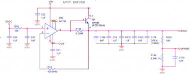
...btw take a look at the offset divider as well
Yep. Advised AKM that some people will probably be trying that with AK4499 too (now that the issue is out in the open at ASR).
Interesting implications with that effect. I kind of assume its the opamps that like it better that way. Haven't tried to test that idea though.
Jens, good point. I will try to take a look a bit later when I have the scope set up by the dac.
BTW, if you have the EVM manual, you may find that Acrobat Reader doesn't display some of the fonts properly on the schematic around dac chip area. Turns out Google Chrome has the correct fonts and will display the text properly if the pdf is opened in it.
EDIT: Also, for anyone who may be interested: I have settled on using JLsounds I2SoverUSB as the USB board of choice with the lowest jitter of those options I tried. None of the boards with plug-in clocks fared very well. The USB board is mounted very near the I2S connector on the eval board, and with the USB board ground plane side pointed towards the dac chip. The USB board is wired to drive all 4-channels of the dac. However that seems to interfere with automatic PCM/DSD mode detection, so at this point I am configuring that manually. Eventually, it should be automated by the MCU using data from the USB board.
In other news, I found a way to reduce LF distortion on the eval board without otherwise hurting sound quality. The Jung regulator by default seems to sound best with the existing dac resistor and cap network. When the network is changed to reduce LF distortion, some other aspects of SQ worsen. Found a simple fix, but the IP used belongs to Jam, not me, so can't share it as of the moment.
Last edited:
Hi Mark,
I think you made an answer to a text, which I deleted in the meantime. I misread the peak currents from the datasheet. So no problem really. Sorry for the confusion.
I think the regulator AKM use is relatively noisy, due to the op-amp used. That is probably why they use series resistors and large capacitors. With other regulators the noise can be much lower.
I think the regulator AKM use is relatively noisy, due to the op-amp used. That is probably why they use series resistors and large capacitors. With other regulators the noise can be much lower.
Not so sure noise is the reason. The eval board sounds very good as-is, subjectively speaking. I think they tuned that supply, including the resistors and caps to give the particular sound it has. Almost any change to the Reference Voltage supply makes it sound subjectively worse in some way. The dynamics of transients get lost and it sounds 'flat,' or it gets too bright and clinical, or some other thing gets worse. I would suggest to carefully listen to the eval board and try proposed changes against its sound to make sure they are really overall better. They make that easy to do, as they no doubt know many people will probably be thinking of using LDOs there. Very easily a mistake if sufficient care is not taken to preserve the best of what the dac can subjectively do.
Last edited:
Not so sure noise is the reason. The eval board sounds very good as-is, subjectively speaking. I think they tuned that supply, including the resistors and caps to give the particular sound it has. Almost any change to the Reference Voltage supply makes it sound subjectively worse in some way. The dynamics of transients get lost and it sounds 'flat,' or it gets too bright and clinical, or some other thing gets worse. I would suggest to carefully listen to the eval board and try proposed changes against its sound to make sure they are really overall better. They make that easy to do, as they no doubt know many people will probably be thinking of using LDOs there. Very easily a mistake if sufficient care is not taken to preserve the best of what the dac can subjectively do.
The VREF regulators need replacing. Voltage ref is a 2.5V zener biased with approx 5mA, bypassed with 100u cap, add noisy opamp.
The analog designers were out to lunch on this one.
- Home
- Source & Line
- Digital Line Level
- ES9038Q2M Board