@888777
My personal opinion about LM317/337 is that they are mandatory for a cheap dac design. There are a lot of LDO's in all DAC schematics (VDD, VDcore, AVCC, AVCA etc.) and they only need aprox. 0.5V for running at their full power specifications. Powering them with higher voltage increases the heat around the circuit. LM3x7s are the best solution to avoid that. Ordering transformers with many precise voltage windings might be an elegant solution, but also an expensive one. So, I prefer to keep the heat away, on the LM3x7 radiators.
My personal opinion about LM317/337 is that they are mandatory for a cheap dac design. There are a lot of LDO's in all DAC schematics (VDD, VDcore, AVCC, AVCA etc.) and they only need aprox. 0.5V for running at their full power specifications. Powering them with higher voltage increases the heat around the circuit. LM3x7s are the best solution to avoid that. Ordering transformers with many precise voltage windings might be an elegant solution, but also an expensive one. So, I prefer to keep the heat away, on the LM3x7 radiators.
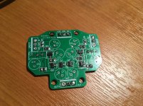
But there is no scheme and you can’t see what's what on the photo ... So I’m not risking buying.
I actually have one of those here and sketched out most of the schematic. It is not as good as a Jung regulator, and not the right design for AVCC. Might be usable for +-15v, but maybe with a pre-regulator.
@888777
My personal opinion about LM317/337 is that they are mandatory for a cheap dac design.
I would agree they make sense as one option for pre-regulators.
a while ago I mentioned the use of LM317 based Nazar's shunt regulators. 317 there has a triple function of pre-regulator, ripple dumper, and a reference. Put it dual voltage version for I/V and LPF opamps with some 30mA current and there won't be a need for ridiculous capacity film caps there.
Since I am sick and I have been staying home the past couple of days, I have made so many steps further into my project as in a 3 or 4 week-ends probably.
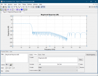
Here is my first custom FIR interpolation filter. It is also linear phase, but it is not so vibrant as built in Slow Roll-off filter and it is not so laid back as built in Fast Roll off filter. The next filter will be an "Apodizing" one, as in ES9038Q2M, but I have to figure out how to also keep the phase linearity.
Here is my first custom FIR interpolation filter. It is also linear phase, but it is not so vibrant as built in Slow Roll-off filter and it is not so laid back as built in Fast Roll off filter. The next filter will be an "Apodizing" one, as in ES9038Q2M, but I have to figure out how to also keep the phase linearity.
Attachments
as I said, there is no need for ridiculous capacity film caps there. I really doubt whether you have paid attention that 3-transistor version has about 5mOhm FLAT impedance over the audio range and some -120db PSRR. if you wish I can send you little pcb with smd soldered.
just tell me what voltage and load you prefer.
just tell me what voltage and load you prefer.
Attachments
Actually, I already have some other power supplies to test here that are reputed to be very good. It is a matter of getting around to making that a priority for the time I have to spend on this. Also, I think Allo will be coming out with a linear supply for Katana that they think will have low impedance across the audio range, ultra-low noise the best ever published for a linear power supply, etc. So, no doubt time will tell. In the meantime I can only recommend what I have tried myself. I do know there are other ways, for sure, but 5m ohms seems silly because the wires going to different opamps could have more than that. The only way to really make it super low at the pins off all devices would be use multilayer boards with ground and power planes. So far as I know that is undisputed. Also, I don't know if there is a ready source of prebuilt boards like you recommend. There are people here than simply will not do SMD soldering, even if they had boards and parts. They do feel comfortable they can solder some film caps together and that counts for something too. I guess if after all above you still want me to try one you could send me one for +-15 output and AVCC supplies, and I could add it to the other ones I have lined up to try. I would also mention there is a article at Linear Audio comparing measurements and listening tests with many different high performance power supplies for audio. Since it was written, already two of the ones they say were best are no longer made, maybe another problem for making recommendations. At least, Wima mks4 will probably be around for awhile. For more info, some possible reading: Linear Audio | your tech audio resource
Last edited:
as for the Nazar's the simulation and measurements you can find here: Nazar vs Salas_Output Impedance: アナログ回路のおもちゃ箱
regarding other concerns, its entirely your call what restrictions you implement in your designs. in fact it was just my offer to you try out something really energy inefficient what would be immediately dismissed in our eco age, but sounding so sweet. i am not interested neither in the promotion of particular power solution, nor in a positive feedback here. your references to any of AD/LA/TI etc material in this respect is irrelevant because of such designs as above do not qualify the primary criteria of modern practices. but do we care about the couple of wats wasted? so, again why then I am posting here? just to say that there are alternatives to use of ridiculous capacity film caps, and they are implemented using LM317 in an original way, not just as a "pre-regulator".
regarding other concerns, its entirely your call what restrictions you implement in your designs. in fact it was just my offer to you try out something really energy inefficient what would be immediately dismissed in our eco age, but sounding so sweet. i am not interested neither in the promotion of particular power solution, nor in a positive feedback here. your references to any of AD/LA/TI etc material in this respect is irrelevant because of such designs as above do not qualify the primary criteria of modern practices. but do we care about the couple of wats wasted? so, again why then I am posting here? just to say that there are alternatives to use of ridiculous capacity film caps, and they are implemented using LM317 in an original way, not just as a "pre-regulator".
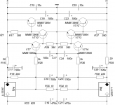
Looks like Nazar's regulator is using LM317/LM337 as the current source for a shunt regulator. However, the shunt devices are 2n3904 or 2n3906 depending on supply output polarity. If I have found the right information, do you think they have any benefits for sound quality as compared to other good shunt regulator designs? Obviously, they have some benefit of simplicity when a small shunt regulator will do.
basically I have design as shown here:
FIRDACmicro или TrueAnalog или GreenDAC
the shunt transistor type depends on how much power it should deal with, so current set by R15/39 and output voltage. their value can be calculated R=(1.25-Ueb)/(0.3/Uout)+Iload
Ueb typically 0.65V, 0.3 stands for the max wattage of the transistor in this case. so if one wants to pump more current then something like BD139/140 should be used. LMs need some 4V overhead, and the whole thing radiates a little heat. anyway, the noise is in uV range, but the impedance is what rules. elcaps better not very low ESR, the reg may start to oscillate. ceramics perhaps better np0, but i am fine with x7r so far
Attachments
Thank you guys, @ Thorp, @ Markw4
What can you advise from the regulators on the LM317 / LM 337? LM317t LM337t Linear Adjustable Filter Voltage Regulator DC Power Supply Board Filtering Electronic Production DIY Kits 317 337-in Replacement Parts & Accessories from Consumer Electronics on Aliexpress.com | Alibaba Group is it
Also, what do you think about this for AVCC TPS7A4700 Low Noise Power Module RF Audio Board 3V 3.3V 5V 12V 15V 1A Adjustable-in Integrated Circuits from Electronic Components & Supplies on Aliexpress.com | Alibaba Group
Mark, I actually would solder and smd elements. But I repeat - where I live at the moment there is no access to details. I would unsolder the same LT1763 on the SOP8 shawl. I have already purchased radio components on aliexpress many times. Hoping for a miracle) But the result is the same - a lot of fakes and marriage. A waste of time and money. ((
Therefore, I order ready-made modules. Slag is less common.
I went over for the sake of interest amplifiers and preamps of Japanese origin. In search of good details ... All regulators are 78/79 05 09 12 15. Yes, the capacitors are real elna)) In general, I did not find anything for the regulator on the power supply. Sorry for offtopic.
I also want to ask for advice) 115V 230V 30W R Core Transformer 18V+18V 9V+9V+9V for Audio Amplifier Preamps AMP DAC R Core-in Transformers from Home Improvement on Aliexpress.com | Alibaba Group -
Does it make sense to take a p-core transformer? if so, will it be correct that the windings for the analogue and the numbers will be on the same core? Will there be any interference with the digit in the analog .. or vice versa? Or does it make sense to take a separate trance for analogue and separately for a number? What does a torr look like against a p-core? and is 0.3A enough for the digital part? (AVCC, clock, other DAC power lines
) Or is it desirable to have a supply of 0.5A current each?
Thank you guys, @ Thorp, @ Markw4
What can you advise from the regulators on the LM317 / LM 337? LM317t LM337t Linear Adjustable Filter Voltage Regulator DC Power Supply Board Filtering Electronic Production DIY Kits 317 337-in Replacement Parts & Accessories from Consumer Electronics on Aliexpress.com | Alibaba Group is it
Also, what do you think about this for AVCC TPS7A4700 Low Noise Power Module RF Audio Board 3V 3.3V 5V 12V 15V 1A Adjustable-in Integrated Circuits from Electronic Components & Supplies on Aliexpress.com | Alibaba Group
Mark, I actually would solder and smd elements. But I repeat - where I live at the moment there is no access to details. I would unsolder the same LT1763 on the SOP8 shawl. I have already purchased radio components on aliexpress many times. Hoping for a miracle) But the result is the same - a lot of fakes and marriage. A waste of time and money. ((
Therefore, I order ready-made modules. Slag is less common.
I went over for the sake of interest amplifiers and preamps of Japanese origin. In search of good details ... All regulators are 78/79 05 09 12 15. Yes, the capacitors are real elna)) In general, I did not find anything for the regulator on the power supply. Sorry for offtopic.
I also want to ask for advice) 115V 230V 30W R Core Transformer 18V+18V 9V+9V+9V for Audio Amplifier Preamps AMP DAC R Core-in Transformers from Home Improvement on Aliexpress.com | Alibaba Group -
Does it make sense to take a p-core transformer? if so, will it be correct that the windings for the analogue and the numbers will be on the same core? Will there be any interference with the digit in the analog .. or vice versa? Or does it make sense to take a separate trance for analogue and separately for a number? What does a torr look like against a p-core? and is 0.3A enough for the digital part? (AVCC, clock, other DAC power lines
) Or is it desirable to have a supply of 0.5A current each?
I`m sorry. Not a "number", it is а "digital part".
Another point is also interesting. Does it make sense to use this filter for AC voltage - AIYIMA 3900W EMI 18A High Frequency Power Filter Power supply Assembled Board For Speaker Amplifier-in Amplifier from Consumer Electronics on Aliexpress.com | Alibaba Group Would it be good with this? If it does, I won't buy anyway. It is in the power supply for computers. Mount not for long.
@888777,
The voltage regulators and R-core transformer you linked to all look okay. However, LM317/337 regulators aren't that good by themselves. You would probably still have some line ripple at the output and the regulation might be okay, but not great for a high quality dac. I can say that I tested Allo Katana using +-15v regulators about like that, but Katana has more internal regulators on the dac board and MCU board, so the LM317/337 wasn't the only regulator, it was acting as a first stage of regulation or a pre-regulator. It was at that stage, the output of the LM317/337 type supply that I added film caps to improve sound quality. As a passive solution that can be added on without concern of oscillation, it just works. Overall I think those things should work much better for you than the original board. If possible, you might find some improvement putting the dac chip VCCA and DVCC pins on another new 3.3v regulator, and leave the MCU on the old AMS1117 3.3v regulator as ESS recommends. Clock can be on the same regulator as VCCA. But, none of those things is as critical as AVCC, and it is better to use two AVCC regulators, one for each channel. Regulators for other dac pins and the clock do make audible differences although they are small-ish differences compared to good AVCC regulators, but on the other hand all the extra options also add to cost and complexity so depends on how much you want to do.
EDIT: regarding the line filter, those things can help depending on line noise where you are. They can help to keep conducted RFI/EMI from getting into the dac through the power supplies. However, that one is pretty minimal. Good power conditioners like the ones Monster used to make can really help audio system sound quality through multiple mechanisms (as compared to a simple HF filter), but they are expensive so most people will probably forego them.
Last edited:
You can show me a clear example of 317/337 on some link ebay or ali. So that I have an idea what to focus on? For the price within reason of course))
And you did not comment on the moment that the windings supplying the analog part and the digital part of the DAC will be on the same core. How bad it is.
Or in this project it will not play a role?
And you did not comment on the moment that the windings supplying the analog part and the digital part of the DAC will be on the same core. How bad it is.
Or in this project it will not play a role?
After all, if we are talking about clean nutrition. That it is necessary to embrace all moments concerning this question. Due to the fact that any signals of "interference" or something else like this can be transferred from the winding to the winding, as they are wound on one core. But here I do not understand what types of "interference" can be transmitted when powering this DAC.
Perhaps there will not be any interference here) Actually, I don’t want to create additional “noises” while trying to get rid of them)
For example, I now have a torr. 24-0-24 with a large amperage, 12-0-12 with a large amperage and 15-0-15 with a small amperage (did not measure, but the thickness of the wires clearly hints at this). This torr feeds the mx50-se amplifier: this is 24-0-24. 12-0-12 are used to power the preamp.
That's the question) - and by powering the DAC from the 15-0-15 line on the same torus, I may be able to create "unfavorable" conditions for powering the DAC ??? Or will the AVCC power regulators do their work and “keep out” noises in the digital signal?
With regards to p-core too. It will power both analog and digital. If you take one p-core, not two. If you have any thoughts - I will be glad to hear.
You can show me a clear example of 317/337 on some link ebay or ali. So that I have an idea what to focus on? For the price within reason of course))
And you did not comment on the moment that the windings supplying the analog part and the digital part of the DAC will be on the same core. How bad it is.
It is possible to have on power supplies on one transformer core. What may be more important is for the transformer to be have more current capacity than you expect will be needed. Transformers have a property called 'regulation' which is a measure of how much the output voltage drops as the output current increases. It is much like saying the internal resistance of the transformer windings, which like any resistor will drop more voltage as current is allowed to increase. What matters for you application is that the transformer have good regulation, and that the regulators and filter caps you use for each different voltage output do a good job of keeping electrical noise from getting back into the transformer. After all, even if you have more than one transformer, if the line impedance is high going back to wall socket, then line voltage may be modulated by a load circuit and a load may inject noise back into the line. There is no guarantee that having two transformers would prevent some coupling between supplies in that case. Still, if you prefer, you could use two transformers instead of one. I kind of doubt your dac will be sensitive to the differences that problems will be caused by using only one transformer. But, even if it were you could always add another transformer later if needed to fix any problem.
EDIT: Actually, if using one power transformer with multiple windings, I think I would connect all the grounds together at one point where all power enters the dac board, and at the regulator outputs. But the ground wires should be kept close together going from the dac board back to the regulators so that any circulating currents from the regulator outputs going back towards the power line will be shorted together before the currents ever get to the dac board, and no ground loops of significant area will be formed by the ground wires going from the regulators to the dac board. IIRR, that would be the correct practice in that case. If all the power supplies where isolated enough from stray coupling going back towards the power line, they would come more close to approximating separate batteries that are completely isolated from each other. In that case one would not have to be concerned with possible coupling back through the transformer and towards the power line.
Last edited:
Here is my first custom FIR interpolation filter.
Interesting, but only so much can be done with the internal filters. For best results they would need to go into an FPGA, ideally a low-cost one like Spartan 6. Unfortunately, it is a lot more involved that getting coefficients from Matlab and loading them into the dac filter. More can be done with the PRO chips if they are configured for stereo only then the number of coefficients for custom filters can be doubled, which might actually help some. Even that isn't as good as external filters in combination with upsampling.
- Home
- Source & Line
- Digital Line Level
- ES9038Q2M Board