The one getting hot is this LM7805TC
Okay. So a heat sink is maybe a good idea although most electronics like that can safely work at higher temperatures than would feel comfortable to touch.
The other question would be what are the highest output voltage regulators on your board, and is the 9v transformer high enough to supply those regulators with the input voltage they need?
I use Arduino IDE with STM32 (blue pill) for ES9018K2M (9 USD board from ebay) for code testing purposes. I was inspired from the K2M code provided by HiFiDUINO many years ago and from Dimitri's blog...
Hi Thorp,
Thank you for the info and the pics. Looks nice. Any idea how much this might cost if extended to ES9038Q2M? Just asking in case we have mod'ers who might be interested in something like that if it were available.
Also, one issue to keep in mind with making something like that available, is that ESS would like detailed register information non-public. Certainly that is a requirement of the NDA, and they mark their data sheets as confidential. Mostly, I think they do it do keep competitors from trying to 2nd source ESS dac chips. For whatever reasons, it is something we have to deal with. Precompiled code could be one solution, as could something like an eeprom between software and dac that obfuscates how low level register programming is actually done.
Also, at least the NDA does allow people covered by the NDA to communicate with each other about things that have not been made public. In that regard, it might be helpful if we knew how many people would be willing to go the NDA route if needed, and how many wouldn't. Then some appropriate planning could be done as to how to best proceed.
Hi Markw4,
Unfortunately it is not so easy to buy ESS chips. I bought K2Ms from ebay - aprox. 4 USD each.
Almost all the other parts in this prototype are free samples and I didn't make any cost calculation yet:
-LT6655, LT3042/3045, ADM7150, AD797 from Analog Devices
-Si549, I2C and I2S isolators from Silicon Labs
-542MILF freq. divider from IDT
-C0G caps and mini MELF metal film resistors for I/V and filter stage from Vishay
-Polymer caps from Wurth Elektronik and Panasonic
All these companies and the guys I communicated with are absolute amazing.
For the final project, I will probably sign the NDA, or not, it depends about the tests result. Honestly, I found and read their datasheets, but I will respect their agreement, even if I didn't signed it, so I will use the information only for my personal tests.
I hope for the ESS chips to meet my expectations, even if I am almost convinced that the AD1955 and AK4490/4493 (depending about the music style) are hard to be beaten. Actually I am already thinking to my future AK4499 project, but first I have to finish the ESS one.
Unfortunately it is not so easy to buy ESS chips.
Normally, to get a copy of the NDA and make it active, you have to work with an ESS distributor. They can either give samples or sell small quantities for R&D. ES9038Q2M cost about $15 each in small quantities, and ES9038PRO costs about $75. Minimum order from a distributor could be $150 or so to make it worth their time, but its not a problem getting parts if one decides to go legit with an NDA.
Also, I think you will probably find that ESS made the new Sabre chips sound a lot better, especially if using the default sort of configuration with ASRC and DPLL. It's quite possible to make a great sounding and SOA dac with ES9028PRO or ES9038PRO, with the main reason to go with the PRO chips being the ability to get somewhat lower noise, and maybe to be able to program longer custom interpolation filters using the dac chip DSP hardware. However, external interpolation filtering for PCM is really probably the best the way to go for ESS or AKM dac chips. Also, upsampling for jitter reduction is probably needed if supporting SPDIF sources. There are other ways that work people use with RPi, or with USB (although OS'es can cause problems in many cases if not very careful).
May I ask how you are using the clock divider in your design? Or even better, would you be willing to post a schematic or maybe a block diagram? I am pretty open about sharing what I learn, but if you are thinking about making something to sell then I would understand if you want to keep it to yourself.
Last edited:
I've looked at the unity gain op amps in the first stage in the schematic, and it goes into an lpf on the xlr alternative. That lpf filter is symmetric around ground, but the first opamps revolves around Vref/2. What happens to the signal because of this? Do each op amp acts as a grounding path for signal from the the other op amp? When combining these signals should these signals ideally be combined around Vref/2? If someone you give me some clarification around how this works it would be a lot easier for me to experiment with other solutions further..
How low could the output resistors in the lpf filters be when driving a 10k impedance (using OPA1612A)? I've been playing 1:4 matching transformer between my pc soundcard and nearfield setup, and it makes a very positive impact on the sound. Better dynamics and a slight tube like sound which I really enjoy. Impedance between components obviously plays a big role, I would like to have the dac's ouput impedance as low as possible.
How low could the output resistors in the lpf filters be when driving a 10k impedance (using OPA1612A)? I've been playing 1:4 matching transformer between my pc soundcard and nearfield setup, and it makes a very positive impact on the sound. Better dynamics and a slight tube like sound which I really enjoy. Impedance between components obviously plays a big role, I would like to have the dac's ouput impedance as low as possible.
Hi impuls60,
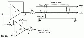
There has been lots of discussion about those balanced outputs since MrSlim added them to the schematic. I personally do not recommend using that method of producing balanced outputs, and have been advising people to add a re-balancing circuit following the unbalanced outputs if balanced outputs are wanted. In most cases the circuits are designed to be symmetrical around ground, although they could be designed to provide symmetry about another common-mode offset. The main reasons for using circuits like these after the unbalanced output it so that the DC offset can be fully removed, and the final output stage filtering can be fully completed.
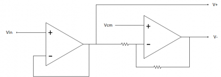
One of the schematics below shows a terminal labeled Vcm, which could be used to create an asymmetrical common-mode offset, but in most cases it would probably be connected to ground.
EDIT: Regarding the improvement in sound quality you notice, the tube-like sound is probably from a little transformer distortion. Other improvements in sound quality would most likely be from minimizing signal return ground loops. At low frequencies ground returns for unbalanced lines will split up and take multiple ground paths depending mostly on the resistance of each path. There are other ways to minimize problems with that, but using balanced signal lines is one way that can work very well.
EDIT 2: Besides opamps as shown below, there are differential line driver chips available (and also differential line receivers) that can provide very high performance solutions.
That Corporation makes some good ones.
There has been lots of discussion about those balanced outputs since MrSlim added them to the schematic. I personally do not recommend using that method of producing balanced outputs, and have been advising people to add a re-balancing circuit following the unbalanced outputs if balanced outputs are wanted. In most cases the circuits are designed to be symmetrical around ground, although they could be designed to provide symmetry about another common-mode offset. The main reasons for using circuits like these after the unbalanced output it so that the DC offset can be fully removed, and the final output stage filtering can be fully completed.
One of the schematics below shows a terminal labeled Vcm, which could be used to create an asymmetrical common-mode offset, but in most cases it would probably be connected to ground.
EDIT: Regarding the improvement in sound quality you notice, the tube-like sound is probably from a little transformer distortion. Other improvements in sound quality would most likely be from minimizing signal return ground loops. At low frequencies ground returns for unbalanced lines will split up and take multiple ground paths depending mostly on the resistance of each path. There are other ways to minimize problems with that, but using balanced signal lines is one way that can work very well.
EDIT 2: Besides opamps as shown below, there are differential line driver chips available (and also differential line receivers) that can provide very high performance solutions.
That Corporation makes some good ones.
Attachments
Last edited:
Regarding listening tests, I did find that the first modded dac I made could be audibly improved by more filtering before the analog outputs. The output stage design that we use now has a lot better filtering at the unbalanced output.
The balanced outputs that MrSlim added to the schematic he drew were basically taken from what ESS was using for their early Sabre evaluation boards. The newer evaluation boards now have additional opamps for the balanced outputs and more filtering, although they still don't use re-balancing circuits.
After I decided I thought re-balancing was probably the best way, I saw a post by the designer of Benchmark DAC-3 who basically said that same things, that the ESS evaluation boards were not doing the balanced outputs the right way and they should balance the signals from the unbalanced outputs.
The other thing I am aware of is that when Allo sent out the first versions of their ES9038Q2M based Katana dac, sound quality was not as good as they had intended. A big part of the fix was to add more filtering to the unbalanced outputs. Since then I think they removed references to the balanced output terminals from the manual, but if people ask if those outputs can be used, Allo says they are like the ESS evaluation boards so you probably should be able to use them. In other words, when asked directly, they kind of sidestep the issue of whether all the filtering for best sound quality will be there.
Probably, the issues we are talking about with sound quality are much smaller than you could see on an oscilloscope. it usually takes at least around .5% distortion to see anything at all on a scope. For old analog scopes maybe twice that, maybe you could see 1% distortion.
Last edited:
Probably worth mentioning that the small amount of DC offset on my DAC disappeared after the balanced output was fully disconnected from the unbalancing/filtering op amp's input, before it was connected like Mr Slims schematic.The main reasons for using circuits like these after the unbalanced output it so that the DC offset can be fully removed, and the final output stage filtering can be fully completed.
Im using the passive filter right now and the sound is full and realistic compared to single ended, it does sound a little strange in a way thats hard to describe, hopefully proper filtering will fix that up.
sounds like a good idea to keep it fully balanced then, DC isnt an issue eitherYou can also use, what is commonly referred to in Pro Audio circles as a 'double balanced' circuit. This was, I believe, first used by a very smart Australian Pro Audio designer, the late Graeme Cohen.
Im using the passive filter right now and the sound is full and realistic compared to single ended, it does sound a little strange in a way thats hard to describe, hopefully proper filtering will fix that up.
May I ask is three are there currently sets of parallel Wima mks4 series film caps on the +-15v power rails to ground? If not, it would be definitely be recommended for audibly better sound quality. Recommended values to solder in parallel for each rail are: 10+10+22+33+33 (all values in uf).
Last edited:
Of course I will share a schematic and the block diagram. As I already told you, it is a test project, so I will share the schematic without any restriction. I only need time, I hope this week-end I will have it.May I ask how you are using the clock divider in your design? Or even better, would you be willing to post a schematic or maybe a block diagram? I am pretty open about sharing what I learn, but if you are thinking about making something to sell then I would understand if you want to keep it to yourself.
wow thats pretty specific and a ton of capacitance for film caps.May I ask is three are there currently sets of parallel Wima mks4 series film caps on the +-15v power rails to ground? If not, it would be definitely be recommended for audibly better sound quality. Recommended values to solder in parallel for each rail are: 10+10+22+33+33 (all values in uf).
A 200uf eletrolytic was added to regulator outputs and
the original 1uf tantalum caps at each op amp were replaced with 0.1 uf polypropylenes, do you really think it would be worth adding all those extra film caps and why?
Last edited:
... do you really think it would be worth adding all those extra film caps and why?
Because I tried it on my dac while trying to reduce sensitivity to different types of opamps that I didn't think should sound as different as they did. Excellent improvement in sound quality.
I later was acting as a reviewer for the new Allo Katana dac. I reported that it didn't sound that good to me using the power supplies recommended by Allo. They suggested I get on with the testing to try to get better sound quality, so I tried it with linear supplies and that helped a lot, but it was still a bit grainy. I told Allo when I could I would try moving my film caps from my dac to the +-15v power inputs on Katana I was feeding with a linear supply. Wow. Really improved it too, the remaining graininess was gone and it was very smooth.
Later I tried again with Katana using mostly 33uf Wima mks4 caps in parallel adding up to about the same value as before. Didn't think it sounded quite as good. During a period when my other block of film caps of various sizes was free for a few days again, I directly compared the blocks of parallel 33uf caps with the mixed value caps and my initial impression was confirmed. The group with some smaller value caps sounded better again. I suspect it has to do with the impedance of the caps at higher audio frequencies. If you look at graphs that Wima publishes for the mks4 film caps, you can see that the larger uf value caps are not specified to as high of frequencies. They kind of go off the bottom of the graph.
Even later, I had a guy over to visit who makes his living as a high end audio designer, including a stint at Pass Labs where he designed their very popular headphone amp that was the hit of one of the CES shows, and sells for $3,500. I told him about my use of film caps in the power supply helping sound quality, and he said with a look on his face like I was dumb, "Well, of course."
EDIT: The film caps were tried only after trying other things with very low ESR electrolytics. We are talking 10,000uf of .053 ohm ESR caps in that case. Didn't help one bit over using 1,000uf electrolytics. But, 108uf of film caps per rail, in the right values, was plenty. Therefore, I recommend trying it, despite the cost. Don't know of another way at the moment to improve sound quality in the same way, although I suspect large area multi-layer PCBs with power and ground planes might be best. I know there are dielectrics that can be added to such PCBs between layers to help lower power supply impedance up to high frequencies. That, and distributed small value lumped capacitors might be ideal.
Last edited:
There is now about 14uf of PP caps per rail and the SQ has improved quite a bit. The main thing I can notice is background sounds are much clearer and front vocals/instruments sound more inline with the background, instead of overlapping, especially during transients, you made a really good discovery thats for sure.
The values used were : 10uf 2.2uf 1uf 0.1uf 22nf 10nf 470pf
I wasnt sure about the extreme low values but threw them in anyway... would have made more sense to add them after the bigger caps to see how much of the difference they account for, if any.
Maybe you tried it already but the leftover caps could be used for AVCC
I have some 22uf Wima caps at the outputs of the AVCC opamp supplies. Haven't A/B compared with using electrolytics in that application.
Regarding film caps on the power rails, after I found out for myself one of the guys who has been around for a long time said it has been discovered and forgotten more than once over the years. Guess people become overconfident that it isn't worth trying or something. Or, maybe some people who don't listen they same way as we do don't notice the difference. Don't know. Seems worth keeping in mind when best sound quality is wanted.
What may actually be new for the first time is the discovery about running AK4137 (or, I suspect, SRC4392) with its clock phase-locked with the Sabre dac clock allows lowest distortion and best sound quality, provided Sabre DPLL is adjusted to take advantage of it.
Last edited:
Here it is, but unfortunately I have no time to make some cosmetics on it. I hope it is readable enough.Of course I will share a schematic and the block diagram. As I already told you, it is a test project, so I will share the schematic without any restriction. I only need time, I hope this week-end I will have it.
Attachments
Here it is...
Thank you. Just took a quick look. It appears you were trying to do a pretty thorough job of giving attention to most all areas of design generally believed helpful for good sound quality and or to prevent problems that could detract from good sound quality.
Since you say it was built for evaluation and not something to sell in the form shown, should we take that to mean there is something about the sound quality that did not meet your requirements? Or, perhaps the cost to make them was more than the market would likely support?
It is only a hobby and I want to build a DAC for my usage (to add it to my DAC's collectionSince you say it was built for evaluation and not something to sell in the form shown, should we take that to mean there is something about the sound quality that did not meet your requirements? Or, perhaps the cost to make them was more than the market would likely support?
") ). The final project (if) will be made with ES9038 (Q2M at least), but for testing purposes I used K2M only because its lower cost. Maybe sometime I will have enough time to put all these prototypes in some cases and to sell them locally in Romania.
). The final project (if) will be made with ES9038 (Q2M at least), but for testing purposes I used K2M only because its lower cost. Maybe sometime I will have enough time to put all these prototypes in some cases and to sell them locally in Romania.Many years ago, my disappointment about ES9018S was named Audio-GD NFB11.32 and that is why I am a little bit cautious (unjustified maybe) about ESS chips.
I decided to build a compact dongle like ES9038Q2M USB->DAC->HPA board. I.e. similar to this The Cyrus soundKey USB DAC transforms your mobile music but not as extremely cheap junk($1 mx250f128 + $1 PCM5102 + $0.5 TPA6130A2 =$2.5), rather with top-rated components. Of course, such compact size means some compromising, CM6642 supports up to 24/192 i.e. DSD DOP64, and tiny PCB has no room for low ESR solid-polymer caps on the power rail. However, one of the top-rated DAC ES9038Q2M + bridged AD8137 and balanced outputs will make that board quite a serious audio performer with up to 350mW/ch@32 Ohm. At bigger PCB I'd like to add 1-2MHz step-up converter for stable 5.5VDC rail, and 5x1000uF solid-polymer caps + XMOS USB audio to get native DSD512 and PCM 32/384 but for a dongle like device I believe the described configuration is optimal.
Attachments
- Home
- Source & Line
- Digital Line Level
- ES9038Q2M Board