Sorry, I have not tried PCM1794. On the other hand, by now I could talk at length about ES9038Q2M. It may be worth noting that the latter part can be found in dacs priced from about $40 up to around $4,000. The q2m dac chip itself costs about $15 in small quantities, so that can't account for most of the cost of many such dacs. Some people think it should be possible to produce a really good q2m dac that sells for $100 - $200. I would have to disagree with that, IME. Short of diy'ing, probably the real cost to get into what I would consider to be good sound quality would come out to closer to $500, and for that you probably wouldn't get a case, SPDIF, or USB, rather it would be an RPi hat type. Easy to spend a lot more than that too with no guarantee of better sound quality.
It turns out the explanation for the huge range of possible dac prices and the possible levels of sound quality has to do with everything, not mainly the dac chip. The right dac chip makes a very good dac possible, but it is only one necessary piece of the whole puzzle. Regarding the rest of the puzzle, there is more than one possible solution to end up with a very good dac, but somehow or other a number of problems need to be solved. Clocking, jitter, quality of various power supplies supporting different circuit functions, configuration of dac control registers, output stage, etc. To get the best sound quality, pretty much everything has to be as good as the designer can figure out how to make it.
The next thing that usually comes up is why in today's world of 24-bit dacs that can operate at measured distortion levels below -100dB could it be possible that people, humans, could hear any differences at all? If fact, it is possible to take you favorite CD, rip a track to 16/44 wav, mix in a recording of a brass band at -80dB, and not have anyone be able to hear the mixed-in sound. However, it can also be shown that if a CD were to be mastered without dither, then the resulting distortion (called quantizing noise) can be audible to some people at end of the LSB, down at -96dB or so. Something obviously is going on with human hearing that doesn't quite makes since if we think about hearing in terms of something like linear engineering models.
My best guess at this point is that the above differences in what can be audible is most likely related to whether or not some small sound is highly correlated with the music signal a human listener is focused on. A brass band would be completely uncorrelated, and the truncation distortion (quantizing noise) due to omitting dither is exactly correlated.
If my guess is perhaps close to about right, then one question that might follow would be: if a number of people could hear quantizing noise at -96dB or so because it is correlated with music being listened to, what is the human limit of detection of correlated small sounds in recorded music? So far, I don't know the answer to that. One experiment I did suggests that it is possible very small changes in 2nd or 3rd harmonic distortion of only maybe 1dB or 2dB for distortion that is already down near -120dB may be audible to some people. I know the preceding statement probably sounds absurdly ridiculous to many people, and seems very contrary to prior published hearing research. But then again, its only about 20dB or so below what we already know a reasonable number of people could hear in the form of quantizing noise. Not only that, I still don't know what the detection limit for humans is. I kind of suspect it may be at least another 10dB below what my experiment suggested.
Okay, I am about done for now. The point I wanted to make was that there is probably some overlap possible between sound quality of PCM1794 and ES9038Q2M dacs depending on how particular designs are implemented. I also wanted to take the opportunity to summarize some continually developing thoughts about dacs, sound quality, and human perception. If you would like a better dac than you have now and have some budget for your audio hobby you need to stay within, we might be able help steer you in a helpful direction, but we would need to know more about your interests, available time, budget, sound system goals, etc.
Last edited:
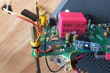
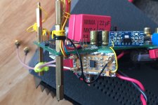
Update on clock divider mod: Turns out I didn't have another LT1763 in stock. Rather than wait to get one I decided to use a little AMS1117 board I had. Also, wanted to be able to switch on/off the LVCMOS to LVDS adapter board to test for any distortion such as I found occurring with the adapter in its previous location, so there is a jumper circled in red (in one pic) behind the regulator to disconnect power for test purposes. In addition, found some damage to a u.fl connector on the adapter board apparently caused during all the repeated assembly/disassembly that goes on when doing tests and performing troubleshooting activities. The connector was replaced and some new coax cables fitted to the board, this time with some strain relief for a couple of them. Pictures below.
Attachments
thank you for explanation Mark
appreciate very much
Interested to know If you have tried pcm1794 dacs offered and If you did what Is your opinion compared to es9038q2m
regards
I've tried the 1794, 38q2m and the 9028pro, all with various degrees of mods.
It is NOT the dac chip itself that determines the quality of sound. It is the implementation as much as the chip itself. No matter how good the chip, a poor set of supporting circuitry will degrade the sound of each chip very markedly. As a result, one cannot truly conclude which chip is the best sounding.
A well implemented older chip can sound better than a poorly implemented top of the line chip. There are many variables including circuit layout itself to really make any conclusion. However do consider the decoding capabilities of the 38q2m versus the 1794 before starting out. One is considerably older and less capable in this area.
I have examples of both running. In both stages of different modding, the 1794 is not as full bodied in sound especially in the midbass and below but the i2S feeding it is not from the same source either and both have different power supplies I hear as large a change in subjective sonic sound character between XMOS USB and Coax than in the sound of the DACs themselves when fed from the same source.
What kind of distortion is audible, it is very puzzling indeed?
Just recently I was able to attach a 20+ years old Assemblage Jittter reduction unit that was made by Sonic Frontiers to my modded 9028pro dac and was very surprised. This made the sound of both Toslink and Coax sound pretty much the same. What was more interesting is that it also allowed TOSLINK and Coax approach the sound of the XMOS USB interface. The XMOS was still superior but the brash sound of jitter was indeed markedly reduced by this old piece of gear. Now when this was attached to the SRC4392 converter that preceded the PCM1794, it did not produce as great an effect. The question then is that, perhaps the SRC4392 has better receiving section than my 9028pro dac. It goes to show, that there is so much that are variables and the effect of any one cannot be discounted.
Last edited:
Today's clock mod update: Clock divider setup is now working without added distortion from power supply issues. However, doesn't sound like jitter is quite as low as I have had it before back when I was bending circuit boards and playing around with ferrites in order to bring ES9038Q2M and AK4137 clocks into relative synchronization.
A couple of possibilities come to mind as possible sources of higher than minimal jitter: (1) added phase noise from LDVS adapters, and maybe from the AMS1117 voltage regulator which is used for one of the adapters, and (2) the fact that MCLK going into the clock divider is coming from a Q2M copy of the MCLK on a GPIO pin rather than more directly from the Crystek clock.
A couple of possible things to try to test the above speculating are (1) a different and maybe a little it better clock divider chip that may not in theory need any added adapters. It is the LTC6954 that Terry Demol found for us. And (2), there might be a clock buffer such as the NB3L553-D clock distribution amplifier that could be inserted between the 100MHz Crystek dac clock and the dac-chip clock input. Then a perhaps more pristine clock signal could be taken from the distribution amplifier to drive the clock divider, rather than relying on an MCLK signal taken from a Q2M GPIO pin.
Hmmm, have to think about it a little more before deciding how to proceed.
Fixed.
Actually, its been awhile since I thought much about this phase of testing, and I just found and quickly fixed a problem. I needed to turn down the digital volume level coming out of the computer a little more since there are two ASRCs in the digital signal path. One in AK4137, and one in ES9038Q2M. So, the master volume level in Windows is turned down about 8dB now, and that completely fixed everything. Before that change Katana sounded better than the modded dac, and after that change Katana sounds worse (with no changes at all to Katana, only the digital volume level before the modded dac). I had completely forgotten about how much difference that can make. Means I may eventually want to pick up some more gain somewhere for the modded dac. Thing about doing it in the I/V transimpedance amplifiers would be is that its better not to have more than 3v peak to peak output swing coming out of the those first stage opamps since that guarantees they are running Class A. Guess at some point gain of the differential summing opamp could be changed, but that would involve recalulating all the filter values. Although maybe free filter design software could make it a simple matter. For not its not a problem for here. Turning up the volume a little after the dac is still doable.
EDIT: It also sounds like jitter may be lower at DSD64 than at DSD256. Currently, we think DPLL = 2 may sound best.
Last edited:
Despite the fact that the modded dac is now sounding much better as a result of adjusting the pre-dac digital signal level, I still think jitter is not the lowest I ever had it. So, I will keep working on it, although I may take a bit of a detour to set up an alternate test system first. We'll see.
Today's clock mod update: Clock divider setup is now working without added distortion from power supply issues. However, doesn't sound like jitter is quite as low as I have had it before back when I was bending circuit boards and playing around with ferrites in order to bring ES9038Q2M and AK4137 clocks into relative synchronization.
Mark, is this the ALVC dual flip flop divider or the original (TI?) one?
A couple of possibilities come to mind as possible sources of higher than minimal jitter: (1) added phase noise from LDVS adapters, and maybe from the AMS1117 voltage regulator which is used for one of the adapters, and (2) the fact that MCLK going into the clock divider is coming from a Q2M copy of the MCLK on a GPIO pin rather than more directly from the Crystek
clock.
WRT LVDS adapter, I would not use it. Keep everything simple.
A couple of possible things to try to test the above speculating are (1) a different and maybe a little it better clock divider chip that may not in theory need any added adapters. It is the LTC6954 that Terry Demol found for us. And (2), there might be a clock buffer such as the NB3L553-D clock distribution amplifier that could be inserted between the 100MHz Crystek dac clock and the dac-chip clock input. Then a perhaps more pristine clock signal could be taken from the distribution amplifier to drive the clock divider, rather than relying on an MCLK signal taken from a Q2M GPIO pin.
Hmmm, have to think about it a little more before deciding how to proceed.
The LTC6954 doesn't really need OP drive buffer and I think if you use the
ALVC dual FF, it also has very good OP drive.
Don't over think this stuff, keep it simple.
If you really want to use a buffer, I know ppl who have had great success
with AD8000 opamp. I'm pretty certain this would have lower jitter than any
CMOS based buffer.
cheers
Terry
Terry,
Currently using the TI LMK1000 divider with some LVDS/LCMOS adapter parts. Next try will be with LTC6954 divider and no adapters. Probably reasonable to expect that could do a little better. Depending on the results, will take it from there.
No hurry though, it sounds very good right now. I can choose to make it sound either almost exactly like Allo Katana dac (a master mode dac with exceptionally low jitter), or a little smoother and less distorted than Katana, but with a little less audibility of low level reverb tails as compared to Katana. (Both Katana and the modded dac are using linear power supplies, supplemented with filter banks of film caps.) The best results I had before gave me both benefits at once, smoother and less distortion than Katana, and with audibility of low level reverb tails equally good as Katana. (Also of possible interest to some people, since Katana operates in master mode, it only works as an RPi hat, whereas the modded dac is being tested with USB, although it can work with RPi, too. Modded dac should be able to work with SPDIF, as well.) For the time being, all listening tests are being done with 16/44 CD rips.
It just seems like since I know I can probably do a little better than I am right now, may as well go ahead and see if I can figure out how to make it a little better. It could be helpful to other dac builders who may come along later to have some information on what has been found to work or not work, at this point in time.
Last edited:
Perhaps a good time to mention that I have been neglecting harmonic distortion compensation with the current output stage, since all my attention has been focused other issues up until now. I think since the clock divider is working reasonably well, it might be a good time for me to get setup to adjust the distortion compensation registers. Will have to get the notch filter out and make sure it is still tuned up as it should be.
Getting the distortion compensation adjustment completed will most likely give a bit more sound quality improvement, in addition to what everything else has already done.
Getting the distortion compensation adjustment completed will most likely give a bit more sound quality improvement, in addition to what everything else has already done.
Last edited:
Interesting es9038q2m board (RPI HAT)
I am not sure if this came up in this long thread before but I just noticed this board on aliexpress which can be found here
From what I see and I might be wrong on some of these:
- Opa1612 opamps
- Seems to have a super-capacitor like the allo boss on the back side of the board (i'm not sure if it's the same)
- some 4 contact points for crystal (behind the headphone output)?
- IR?
- lots of two letter connection points which I have no idea what they are for
Price is more expensive than the boards used here in the thread and it's just the RPI gpio inputs and rca+3.5 outs.
Thoughts?
Offtopic:
Hi Markw4 !
Sorry to bother you but can you help me to implement this DAC board (WM8740 based) and possibly mod it ?
Assembled WM8740+DIR9001 DAC Board Decoder Board (support USB+coaxial)-in Amplifier from Consumer Electronics on Aliexpress.com | Alibaba Group
Here is the thread !
Cheap chi-fi DAC buy (<30 USD)
(I bought it instead of the ESS DIY board you suggested as it had been bought, checked and verified by a friend of mine who sold it to me. I didn't want to deal with a possible DOA and the Aliexpress return process.)
Thoughts?
Hi,
Looks like a lot of stuff for around $50. Still, it is probably at best not much more than $50 dac, IMHO. Looks like it probably has a voltage output stage, DC-DC converter, etc., things that help keep price low, but unfortunately also tend to give low sound quality. Doesn't look easy to mod, either. Think I would pass on that one.
Offtopic:
...can you help me to implement this DAC board (WM8740 based) and possibly mod it ?
Hi eljoantonyn,
Not sure what I could do to help you with that one. I don't have one like it to examine at closely or to listen to.
Of course, things like good power supplies usually help. If you buy some good ones, maybe you could keep them for use on the next dac after this one, whenever that might be.
Was there something specific you had in mind that you wanted to do with it?
Perhaps a good time to mention that I have been neglecting harmonic distortion compensation with the current output stage, since all my attention has been focused other issues up until now. I think since the clock divider is working reasonably well, it might be a good time for me to get setup to adjust the distortion compensation registers. Will have to get the notch filter out and make sure it is still tuned up as it should be.
Getting the distortion compensation adjustment completed will most likely give a bit more sound quality improvement, in addition to what everything else has already done.
I'm pretty sure Benchmark use it. The issue I see is that most opamp
generated distortion will be frequency dependent, so at what freq do you
compensate for?
It gets back to my original recommendation of ADA4898. Because the
opamp is fast, the Freq vs Dist curve is flatter.
The other option is to use a discrete opamp with TPC (two pole
compensation). This compensation has flattest dist versus freq curve.
Or you could bight the bullet and just use Weiss discrete opamp.
Lowest distortion of any opamp I've ever seen - but very pricy.
Too many options
")
T
The thing about harmonic distortion compensation is that it may not matter what you adjust it to using measurements, if you then decide to see whether or not to leave there or change it a little based on listening preferences with real music. Besides, despite whatever ESS says, I'm not so sure that the distortion compensation isn't as much for the dac chip as it is for the output stage. Allo says there is only about 1dB variation in how distortion compensation changes when their Katana dac discrete output stage PCBs are swapped. That tells me all the boards either distort almost perfectly the same, or most of the compensation is really for dac chip.
Regarding opamps, I don't have reason to believe there is much distortion caused by the opamps, and if there is maybe it has to do with power quality, local RF fields, or whatever else that can't be precisely determined from data sheet specs.
According to Chord, they use composite opamps for their DAVE dac, something you forgot to mention in your recommendations above.
Anyway, these Sabre dacs don't have nearly as much really high frequency junk coming out of them as many older dacs do. Therefore, less need for highly junk tolerant amplifiers. We do want distortion as low as we can get it though, down at -130dB or lower for the highest level partials would be great. That would make the amplifiers a bit lower distortion than the dac chip. Not convinced that messing around trying opamps with unknown distortion at audio frequencies is worth wasting my time on at this point, either. I have other issues I want to work on.
However, if you would like to join in with us in modding dacs, that would be great. As soon as you get one fully modded to catch up with where I am, we could strategize about prioritizing areas for further development efforts. When it finally comes around to an updated output stage being the most important thing, then you can be my guest and take that one for yourself to work on. When do you think you can be ready?
Last edited:
Hi,
Looks like a lot of stuff for around $50. Still, it is probably at best not much more than $50 dac, IMHO. Looks like it probably has a voltage output stage, DC-DC converter, etc., things that help keep price low, but unfortunately also tend to give low sound quality. Doesn't look easy to mod, either. Think I would pass on that one.
Thanks Mark!
You are taking this exploration to the Nth degree all right.
Just trying to help make it more common knowledge around here how to make a good Sabre dac. When I started out in this thread, I was looking to help people find some easy ways make better dacs for very low cost. As time went on, I found more and more things that affect sound quality, some only a little, and some quite a bit more. Also found that to end up with a pretty good dac required taking care of even things that only help sound quality a little, because in the aggregate they can add up to make a rather substantial difference. Of course, most of the above is well known by some of the people who have been making dacs for a living or at least for some supplemental income. But, there wasn't anybody here in this sub-forum who was working to separate dac modding fact from fiction in a methodical ongoing way, and making the findings freely available to anyone with any interest. The reason I am still at it is because I know we haven't reached the limit of what is possible even with the little mobile ES9038Q2M dac chip. I do, however, think we are probably getting pretty close to what the dac chip can do in a general-purpose-type-of-dac application. Hopefully, the clock dividing mod can be brought to a satisfactory conclusion pretty soon. If so, the main thing I know of that would be left to figure out would be low-cost external interpolation filtering.
After that, what someone or some group might want to do is work on further optimizing and maybe simplifying some of what we have now that works, but that could perhaps be done at lower cost, or with fewer parts, maybe done a little better, etc. Maybe shrinking the size of what is now rather spread out. Those types of things. There could be a number of benefits from a well designed multi-layer PCB, once some other refinement has been done. A well designed steel case with proper cable management to minimize RFI/EMI incursion could be a good thing. I don't think I will stay involved to the end of what might be done. Part of the reason I keep working on this project as I have is because of my curiosity about about looking into particular issues. Not much left in that list, I don't think. But, don't worry, I won't leave people with partially completed dac mods and no support. I still want to see people have better dacs at lower cost.
Last edited:
- Home
- Source & Line
- Digital Line Level
- ES9038Q2M Board