It's shown in the output stage assembly instructions: Dropbox - Output Stage Instructions.zip Just leave out the holes for DIP sockets and solder the ground traces on the surfboards to the copper foil ground plane you laid down. Pretty easy in that case, almost just use one big piece of copper foil.
I have been told that this dac can procuce over 1V in voltage mode, in current mode several times less, therefore requires enormous amplification.
Maybe it is better to stay in volatage mode?
See my post
https://www.diyaudio.com/forums/digital-line-level/314935-es9038q2m-board-352.html#post5649503
In full voltage mode it can do a bit over 2V RMS (approx) (fully balanced) but it
makes more distortion.
This has been discussed.
See my post
https://www.diyaudio.com/forums/digital-line-level/314935-es9038q2m-board-352.html#post5649503
In full voltage mode it can do a bit over 2V RMS (approx) (fully balanced) but it
makes more distortion.
This has been discussed.
What input sensitivity the amplifier has to have so that I can hear anything out of this dac in current mode with the recomended output stage (MrSlim's Drawing) Will it have the output of modern devices or closed to a phono out?
What input sensitivity the amplifier has to have so that I can hear anything out of this dac in current mode with the recomended output stage (MrSlim's Drawing) Will it have the output of modern devices or closed to a phono out?
You need to study some basic opamp theory about I-V conversion. It's pretty
simple.
Current to voltage converter | Electronics Tutorial
In current out mode the I-V opamp generates a voltage at it's OP.
The IP current swing x feedback resistor size determines OP voltage.
Time to do some studying.
")
cheers
T
@Markw4,
1. Regarding the SMD film caps for AVCC, the only in-stock I found is a Rubycon 10uf at digikey which is very expensive @ nearly $12 per piece. I was thinking of using through hole 10uf Wima you used which is in stock, one for the ltc6655 and two for the opa1612 output (22uf Wima is out of stock in Mouser). Will that be okay?
2. Regarding the proto boards, I found this board (big in size 3.9" x 6.3") which I estimate should fit AVCC and Output stage plus two lt1763 and its components, while adding another second board for the LTC6655 which is MSOP. Links below. Will these work? What do you think?
a. SMT3U BusBoard Prototype Systems | Mouser India
b. LCQT-SSOP20 Aries Electronics | Mouser India
Regards,
Kay.
@Markw4,
1. Regarding the SMD film caps for AVCC, the only in-stock I found is a Rubycon 10uf at digikey which is very expensive @ nearly $12 per piece. I was thinking of using through hole 10uf Wima you used which is in stock, one for the ltc6655 and two for the opa1612 output (22uf Wima is out of stock in Mouser). Will that be okay?
Yes. 10uf at the output is enough to keep most of the opamps ESS tried from oscillating in the AVCC supply circuit. ESS only found one opamp that needed 47uf to be stable. Most likely OPA1612 will be okay with 10uf, but I have only tried it with 22uf myself. If you do find problems with oscillation there you could always add some electrolytic caps in parallel to stop it.
Also, I usually shop at Mouser since I think their prices might be a little lower on average, although DigiKey may keep more variety in stock. You might try checking for caps in stock at Mouser just to see what you can find.
2. Regarding the proto boards, I found this board (big in size 3.9" x 6.3") which I estimate should fit AVCC and Output stage plus two lt1763 and its components, while adding another second board for the LTC6655 which is MSOP. Links below. Will these work? What do you think?
I would suggest looking for proto boards more like I used. You may be able to find them at Amazon, ebay, Aliexpress, etc. For example: AUSTOR 36 Pieces Double Sided PCB Board Prototype Kit, 5 Sizes Universal Printed Circuit Protoboard with Free Box, for DIY Soldering and Electronic Project: Amazon.com: Industrial & Scientific
Regarding adapter boards for small SMD parts, there are many places to buy them. The main thing is that LTC6655 is much smaller than most of the other parts we use, so make sure you get the right size for it. The other thing to be aware of is that some SMD adapter boards are two sided so that they can be used with two sizes of SMD parts. In that case they need to be used with pins, otherwise if they were laid down on top of a ground plane the traces on the bottom of the adapter could short out and cause problems. Drilling out the vias could prevent problems, but something to be aware of and use with care. The extra traces on both sides of the adapters also increase capacitance between device pins which could cause problems with some high frequency or high speed parts. Long pins also add inductance and capacitive coupling between pins, so are not good for fast parts. Using something more like Surfboard and soldering them flat down on a ground plane is probably the best. Sometimes other SMD adapters can be used that way too. However, LTC6655 is not a high speed part, so I didn't worry at all about putting it up on legs (pins) on an adapter board.
If I was unclear about anything, please let me know and I will try to clarify.
Regards,
Mark
Last edited:
I have been told that this dac can procuce over 1V in voltage mode, in current mode several times less, therefore requires enormous amplification.
Maybe it is better to stay in volatage mode?
No, better to use current mode. The output stage design we use has the necessary amplification. No need to worry.
In some ways what matters is signal power, not necessarily just voltage. What can work best depends on the situation. There is enough current coming out of dac when using an I/V output stage that we can convert to voltage without having to worry about noise.
Last edited:
Hi Mark,
The components for my output stage build arrived so I'm ready to build, one question though, where did you get the copper foil.
Paul
Usually from Amazon or ebay. I got a big roll of it from ebay, maybe more than I will ever use. The adhesive backed copper foil sold in most places is all the same stuff, and it is pretty thin. It still works for most purposes okay.
It is possible to buy all different thicknesses and sizes of copper foil made by Scotch, the tape company. The very thick stuff in wide sizes is pretty expensive, hundreds of dollars per roll in some cases.
However, the cheap stuff has been fine so far. Maybe like this: Copper Foil Tape - 6" X 10ft - EMI Conductive Adhesive / Ship from USA | eBay
Parts have been ordered
If you are referring to the little regulators for the dac chip and clock that I soldered to the bottom of the ground plane, we don't need to worry about ground loops for them, since they are on a solid, continuous ground plane.
Regarding the external power supplies, I only use two: There is an external +-15v power supply for the analog circuitry, and an external +5v supply for the digital circuitry and to power LTC6655. My approach to try to minimize interaction between analog and digital ground currents and other effects is to connect the +-15v power and ground return at the analog end of the board, and connect the +5v power and ground return close to or at the digital end of the circuit board. The only place the grounds for both external supplies connect together is at the dac ground plane. Otherwise the two external supplies are completely separate from each other.
I am thinking about making a PCB for the output stage.
1. do you think it is a good idea
2. anyone interested in a group buy?
It could be a good idea if you know how to do it well. For very high performance designs sometimes it can take more than one design iteration to get PCB layouts working optimally. Also, it would be much better to use SMD parts if designing a PCB. Then components can be kept very close to their associated opamps and stray coupling can be minimized. However, if the only way to get folks interested in modding a dac is to offer a through-hole component PCB, then I guess it would be a good idea for one to be available. If laying down through-hole parts on their sides, it might have to be bigger than the output stage board I built. It should still have a ground plane that is connected directly and continuously to the dac board ground plane though.
Last edited:
That may work if the optional display is connected, but may not work without it.
hi,there,
i don't have the display, the ui have everything therefor we don't need that.
cheers
i don't have the display, the ui have everything therefor we don't need that.
Okay, if you say so. I have one of the 1.07 boards and got a display to go with it just to try out. Display never worked with it, and installing J1, J2 did not stop the MCU. Maybe they loaded it with the wrong firmware, don't know. Anyway, it got its pins lifted.
Okay, if you say so. I have one of the 1.07 boards and got a display to go with it just to try out. Display never worked with it, and installing J1, J2 did not stop the MCU. Maybe they loaded it with the wrong firmware, don't know. Anyway, it got its pins lifted.
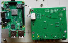
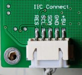
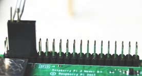
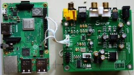
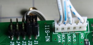
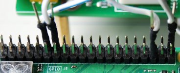
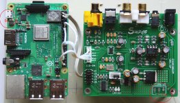
i think you are right, the firmware is wrong, i worked on more than 20 pcs smc cb q2m boards, they are all good, may be just coincidence . here are some photos of my test module, hope they are helpful in starting on q2m modification.
Attachments
Last edited:
- Home
- Source & Line
- Digital Line Level
- ES9038Q2M Board