Yeah, not so easy to get such info. IIRC the OPA197 has it (375 ohms and over 120dB) and might be a good choice for this job. http://www.ti.com/product/OPA197
The NE5532 doesn't declare it specifically but there's enough to work out 120dB, and says Zout is 0.3 ohms at 30dB gain and 10KHz... so that is 0.009 ohms at worst I think, and possibly even lower ... and I have a gazillion of them. ;-)
The NE5532 doesn't declare it specifically but there's enough to work out 120dB, and says Zout is 0.3 ohms at 30dB gain and 10KHz... so that is 0.009 ohms at worst I think, and possibly even lower ... and I have a gazillion of them. ;-)
Last edited:
Hmmm.... well I guess i might try the LM6171 despite the noise - it has a stated Ro of just 14ohms with an open loop gain of 90dB so that would be an output impedance of 0.00042 ohms - quite impressive. Plus the huge slew and fast settling....it has ample current and bandwidth and is unity gain stable, so really it is only noise at 12nV which is a detractor, and that seems to be a little better at lower supply voltages. Over the audio bandwidth to 20KHz, this would be 1.7uV rms noise I think... again... maths ;-) but if I got that right then it is still much lower than the TPS7A49 which is around 12uV over the audio bandwidth. 510 ohm feedback resistor with a 2pF bypass seems to be about it for optimal use. The datasheet doesn't say anything about single rail supply but I assume +12V/GND will be fine with a 5V input/output.
Last edited:
Gah... getting bored of going through datasheets... but I think I found the best one so far - THS4031. Check it out.
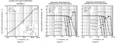
I ran it through Webench as a non-inverting amp with gain of 1.1 running from a single rail 12V and driving 10mA. It'll do 100V/us slew and 100MHz bandwidth and for that it'll have 37uV rms noise. If we imagine that the TPS7A49 was capable of this bandwidth, we might imagine it would have very similar noise. Back in the real world, the TPS has almost zero PSRR at 10MHz. The issues I can't establish through webench are a value for output impedance and how much capacitance it can tolerate.
Here are the relevant charts from the datasheet - 15, 31 and 33 - bandwidth should extend to roughly 10Mhz as a voltage follower and output impedance will be in the very low mR range, if not quite uR. I think I'll try it with no output capacitance at all at first and see how well I can avoid any stray capacitance/inductance. Unfortunately, I've spent so long investigating this I have no time left to build it this weekend :-(
Attachments
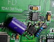
late night, early rise... and I got it built after all. It didn't take long - removed the ceramic decoupling cap on pin5 of the TDA1387, cut the power trace, fit the THS4031 upside down to minimise stray capacitance... etc... and it works well. It's hard to be specific about sound changes without A-B comparison but it seems to have better definition. I think it's worth doing. There's no capacitance on the the output of the THS4031 and the trace between it and the TDA is less than 1cm. Pin6 of the THS, output, has been bent so it sits on the pad where the ceramic was. The THS stays cool, as does the TDA - no more than 8degC above room temperature. There's no signs of oscillations etc. The attached photo was taken before the power connection to 12V so you can see connections - after the 12V power is connected, there is a cap over the top of the THS which obstructs the view of connections. The black paint screens the copper that got exposed when I cut the trace. And yes, I noticed the little blob of solder near the OP42 only after I took the pic ;-)
Attachments
Last edited:
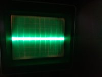
Put it on the scope - that monster MHz wave has gone and now I can see there are sharp faint 40mV spikes at 44KHz (playing 44KHz tunes at full scale output) and the spikes themselves are a 2.8Mhz decaying ring that modulates from 0 to 40mV with the music's amplitude. There's no oscillations on the power rails and overall, the output is looking much cleaner. I'll see if I can reduce the noise further with pF caps on the DAC output and in parallel with the I/V resistor. That's about all that's left to do now anyway.
Last edited:
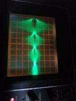
And it's done! 220pF Wima bypass on the 3K I/V resistors sounds fine. Actually sounds better than the es9018k2m... pretty impressive given an almost 30 year gap in tech between them. Here are the scope pics from earlier. I expect they would be better now but whatever. The 44KHz noise:
2.8MHz noise
An externally hosted image should be here but it was not working when we last tested it.
2.8MHz noise
An externally hosted image should be here but it was not working when we last tested it.
Good stuff Hugh, but I can´t see any of your measurements (I´d like to). Indeed this is a good option for low power consumers such as the tda1387 and tda1545.
My friend Jocko Homo would probably use green leds for the reference, with a CCS made of one DNMOS or NJFET. He seems to be concerned with noise at very low frequencies, always. I should do some experiments and try to hear the differences. Measuring sub-Hz stuff is hard and very time consuming.
Thanks
Alex
Yeah sorry, no measurements, I don't have the gear to do them, and I guess that this wouldn't measure that well anyway given the numbers in the datasheet aren't impressive by modern standards.
Yes, that filter needs a low leakage cap but the Oscon is the only small 47u I had so I didn't even think about it ;-) I'm not sure I'd actually hear a difference though - I cannot hear any background noise at all. Maybe just squeeze out a little more resolution. Anyway, it should be quite easy to replace so thanks for pointing that out. I have yet to finish the buffer op amp resistors so I'll replace the Oscon when I do them.
Yes, that filter needs a low leakage cap but the Oscon is the only small 47u I had so I didn't even think about it ;-) I'm not sure I'd actually hear a difference though - I cannot hear any background noise at all. Maybe just squeeze out a little more resolution. Anyway, it should be quite easy to replace so thanks for pointing that out. I have yet to finish the buffer op amp resistors so I'll replace the Oscon when I do them.
Last edited:
Hugh, some of your attachments can´t be seen, at least by me. If I copy and paste the URL I get this:
Thanks
Alex
This site is marked private by its owner. If you would like to view it, you’ll need two things:
A WordPress.com account. Don’t have an account? All you need is an email address and password — register here!
Permission from the site owner. Once you've created an account, log in and revisit this screen to request an invite.
Thanks
Alex
Yes - that's Wordpress' security. Sorry. Here they are as attachments. Not great and arguably would still create audible IMD, but much cleaner after fitting the THS4031. The MHz noise coming out of the IC went from a constant 400mV to an output modulated and decaying/ringing 40mV peak to peak
Attachments
Last edited:
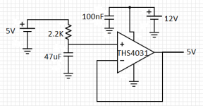
Let the fun begin! I whipped up a quick schematic for you, see attached.
I wasn't gone, just got the ICs in my box! I just need the SOP8 to DIP8 boards now and will start soldering the very basic implementation asap. Will keep you posted. TY again.
Hey Matt, I have all the pieces, starting to build this basic implementation from page 30 on a breadboard. Already soldered the DAC into a socket converter to make it easier to work with.
Sorry I think this is the most stupid question, but RIGHT and LEFT should be used with a GROUND as well, right? So, one cable using ground and LEFT to the left amp input, and the other cable using ground and RIGHT to the right amp input. I have some spare RCA cables I can cut and reuse, if this is correct.
Thank you
Hopefully "TO_RIGHT_AMP_CHANNEL" and "TO_LEFT_AMP_CHANNEL" are self-explanatory.
(...)
Let me know if you have any questions!
Sorry I think this is the most stupid question, but RIGHT and LEFT should be used with a GROUND as well, right? So, one cable using ground and LEFT to the left amp input, and the other cable using ground and RIGHT to the right amp input. I have some spare RCA cables I can cut and reuse, if this is correct.
Thank you
- Home
- Source & Line
- Digital Line Level
- tda1387 dac pcb "front end"