OK I'm salvaging like crazy. Will show my complete ignorance now, hope you bear w/ me. Is there a way to know the value of these kind of caps below?
View attachment 710428
Thank you
No numbers? No idea, sorry.
The i/v filtering on my little giant is done - it might benefit from some minor tweaking (e.g. reducing 2.4nF to "taste") but this certainly satisfies my ears.
2.4nF Relcap RTE on top of the DAC IC - one for L and one for R - to filter the DAC output.
15pF NPO bypass on the I/V resistors.
I already bypassed the AC coupling caps, etc as mentioned before.
An externally hosted image should be here but it was not working when we last tested it.
Last edited:
Kudo's Matt. For part of the day I have been listening to the TDA1387 through Sy's Impasse preamp into a Pass M2. Good sounding.
My fav is the Pass BA-3 preamp into a pair of bridged Pass F4 amps. Even better sounding.
For the office, the desktop computer is connected through an Uptone Regen into a SMSL M8a with an external linear power supply. Audio files are .flac played via JRiver.
I synced two audio files of the same song and switched between inputs on the BA-3. For the cost of a Pi and your TDA1387 Dac vs the cost of the M8a with the extras, the cheaper rig holds its own in my system.
I have order a Kali to go along with the Dac.
Good stuff!!
What SA did you get?
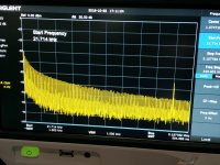
Its a Siglent SSA3021X. Here's the first picture of it in action. The plot is directly out of one channel of a TDA1387 on my lingDAC's DAC board. The analyser input impedance is 50ohm and the current swing is 1.2mA p-p. The DAC's playing back an 11.025kHz sinewave at full level and we're looking at a frequency band from 22kHz to 3.1MHz over which the signal level has dropped about 40dB. The peak near the far right end turns out to be from the BCK (2.82MHz).
Attachments
Super, Stellar. Thanks, I have a Kali ordered. Yep my problem was in the build, not Volumio. Like you I enjoy the simplicity and not being familiar with Linux doesn't help.
I am on the fence for power, I am following Ian's design/build of the battery supply with interest. You mentioned Greg S. and his Jameco modified supplies. Any word on those?
Thanks
David
I am on the fence for power, I am following Ian's design/build of the battery supply with interest. You mentioned Greg S. and his Jameco modified supplies. Any word on those?
Thanks
David
Its a Siglent SSA3021X. Here's the first picture of it in action. The plot is directly out of one channel of a TDA1387 on my lingDAC's DAC board. The analyser input impedance is 50ohm and the current swing is 1.2mA p-p. The DAC's playing back an 11.025kHz sinewave at full level and we're looking at a frequency band from 22kHz to 3.1MHz over which the signal level has dropped about 40dB. The peak near the far right end turns out to be from the BCK (2.82MHz).
Nice tool
") -30db to -70db with a -55dB hump at 2.8Mhz.... my high frequency bump was double that at 5.5MHz, which is higher than the chart shows.... good to see no other major bumps but I still wonder what, if anything, lurks higher nearer the DAC f clock. More to the point - the chip needs filtering on the output pins
-30db to -70db with a -55dB hump at 2.8Mhz.... my high frequency bump was double that at 5.5MHz, which is higher than the chart shows.... good to see no other major bumps but I still wonder what, if anything, lurks higher nearer the DAC f clock. More to the point - the chip needs filtering on the output pins
Last edited:
2.4nF Relcap RTE on top of the DAC IC - one for L and one for R - to filter the DAC output.
15pF NPO bypass on the I/V resistors.
I already bypassed the AC coupling caps, etc as mentioned before.
An externally hosted image should be here but it was not working when we last tested it.
Going through basic SIMS, trying them out, listening, putting it on the scope...
I've got a hypothesis that the DAC IC in this little (I think he must mean gentle) giant doesn't like a "big" poly 2.4nF cap directly on its pins - I've removed it and will try smaller values of silver mica. It also doesn't like an I/V resistor over about 3K. I tried up to 5.6k but got tiny amounts of faint distortion on the quiet decay of cymbals etc.
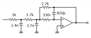
The best sound I've got so far is changing the buffer into a third order filter like the attached (it was second order with a gain of -1.6), with no cap on the DAC IC and a 15pF bypass on the 3K I/V resistor. I've run out of small pf caps so I've ordered more and will keep testing. The extra 1k resistor fits where the grey ac coupling cap was originally. Also, I forgot to edit the pic to show that the op amp +ve input is not ground but has about -0.85V input, so the DAC is DC coupled with 0.something mV output offset, into a DC coupled headphone amp driving HD650. This avoids "signal degrading coupling capacitors" as Ti Kan says on his AMB website.
Attachments
Last edited:
Going through basic SIMS, trying them out, listening, putting it on the scope...
I've got a hypothesis that the DAC IC in this little (I think he must mean gentle) giant doesn't like a "big" poly 2.4nF cap directly on its pins - I've removed it and will try smaller values of silver mica. It also doesn't like an I/V resistor over about 3K. I tried up to 5.6k but got tiny amounts of faint distortion on the quiet decay of cymbals etc.
The best sound I've got so far is changing the buffer into a third order filter like the attached (it was second order with a gain of -1.6), with no cap on the DAC IC and a 15pF bypass on the 3K I/V resistor. I've run out of small pf caps so I've ordered more and will keep testing. The extra 1k resistor fits where the grey ac coupling cap was originally. Also, I forgot to edit the pic to show that the op amp +ve input is not ground but has about -0.85V input, so the DAC is DC coupled with 0.something mV output offset, into a DC coupled headphone amp driving HD650. This avoids "signal degrading coupling capacitors" as Ti Kan says on his AMB website.
Hi Hugh,
My "little giant" had a long way to go to equal my AK4490, or my ESS9023 subbu dac based on a cheap dac chip. the subbu was neck and neck with the AK4490. I'd be interested in your impressions of the improvements after your through with your tweaking compared to a well recieved delta sigma oversampling DAC. I'm going to dig through my parts bin to see if I have anything on hand to implement some of the modifications you've tried so far, the first of course to bypass the coupling caps. It would be a nice little dac if one could bring out more detail and background clarity.
Trimming out the DC offset to enable direct coupling seems like a great solution that gives total clarity and also saves the $ one might spend on expensive film caps that can only approach this level of transparency. I wonder why this isn't used more frequently. I also am not sure if my cheap multimeter is precise enough to do this myself.
Hi Hugh,
My "little giant" had a long way to go to equal my AK4490, or my ESS9023 subbu dac based on a cheap dac chip. the subbu was neck and neck with the AK4490. I'd be interested in your impressions of the improvements after your through with your tweaking compared to a well recieved delta sigma oversampling DAC. I'm going to dig through my parts bin to see if I have anything on hand to implement some of the modifications you've tried so far, the first of course to bypass the coupling caps. It would be a nice little dac if one could bring out more detail and background clarity.
I'm going back and forth between DACs trying to get one to beat another. It's currently competing with an ES9018k2m which has a level of dynamics, detail retrieval and definition that exceeds the TDA1387. However, the TDA has a pleasant signature so I quite enjoy listening to it... fun to keep trying anyway.
Trimming out the DC offset to enable direct coupling seems like a great solution that gives total clarity and also saves the $ one might spend on expensive film caps that can only approach this level of transparency. I wonder why this isn't used more frequently. I also am not sure if my cheap multimeter is precise enough to do this myself.
I wonder too. Perhaps it's because many engineers on Diyaudio will say it's impossible to hear an electro coupling cap, given it is large enough to not be creating any distortion, so they are happy to stick one in the path, several in fact, and even say that a small polypropylene bypass is futile.
Also, it does create small pops at start up and shut down and most engineers would not tolerate this, but for builders, it's not difficult to add speaker protection with delays so this never gets heard.
If we add DC, then, in addition to the same voltage on both inputs, we also want similar current on both op amp inputs. The inverting input of my current set up has 2.7K on the input and 2.7K in the feedback loop and this is dropping -1.7V (a 3K resistor sets I/V output at -1.7V, and the buffer output wants to be trimmed to 0V, with 5.4k in between). That's about 315uA I think. Using the -12V rail as my source for the non-inverting input's -0.85V (pin3), I should have 38K as my pot. Actually I have a 10k pot and a 10k resistor for 20K, so I'll change them. I'll put 2.7K between pin3 and gnd with a 1uF filter cap in parallel, and use a 10K trimmer (set to 5k) and 30k resistor in series between -12V and pin 3. So 35k (+/-5k) goes from -12V to pin3 and 2.7k goes from pin3 to ground, with a filter cap of 1uf. I hope that's right - it's early and I need coffee.
I'm using a Fluke DMM and pretty much any DMM that can read mV is fine to do this job, but of course, the more accurate the better. Worth measuring the resistors too or using 1% or better. Lifting the op amp pin3 up to disconnect it from ground without damaging the op amp leg is the trickiest part of the job to me.
Last edited:
To me, 1387 has a very expressive, dynamic and realistically-textured sound signature that does not highlight low-level minutiae in the recording. As a result, when it is fed quiet power, it can feel spatially to be in a bit of a black hole, as some of those cues seem to be below the threshold of its resolution. The transients definitely become snappier when the treble droop is corrected, and then some ambience illuminates the stage as well.
Last edited:
Realistic texture is a good way to describe it.
However, I definitely think dynamics are lacking compared to to other DACs and I have assumed this to be because the gentle giant is running from a TPS7a49 - its noise is low enough at roughly 15uV but perhaps its output impedance is holding the DAC back. I have been thinking about cutting the short fat trace and inserting a voltage follower op amp after the regulator to create a low source impedance to drive the TDA. It looks like there is just enough space to add one. Has anyone tried this? Or have you tried another way to implement a low impedance and low noise supply and noticed a big difference to dynamics over a 150mA ldo?
In this pic, the trace is in the bottom left corner - the fat one running from a yellow tantalum to the right of the DAC, down and to the left to a ceramic next to and below the DAC.
Last edited:
Or have you tried another way to implement a low impedance and low noise supply and noticed a big difference to dynamics over a 150mA ldo?
Dynamics in the bass comes from a lower impedance supply, dynamics in general will improve with better OOB filtering. But not all low impedance supplies are equal. The lingDAC DAC power supply schematic (see link below) has Zout well under 1ohm and it does better than a TL431 shunt reg with lower Zout. Its also much lower noise (not hard to better a TL431 though). Haven't tried a 150mA ldo.
lingDAC - cost effective RBCD multibit DAC design
The TPS7A49 output impedance is around 0.013 ohms if my maths is correct...it sometimes isn't ;-) I don't like the bandwidth plots - reminds me of 78XX which sound dull in the treble range. A follower op amp using something like LM6171 should be even lower and hopefully in the uR not mR range and have a huge bandwidth, plus it creates a low source impedance so that makes the preceeding regulator less relevant.
Last edited:
So the TDA1387 uses less than 10mA it seems. So pretty much any unity gain stable op amp can achieve this. What I need is a decent open loop performance - gain, say 120dB, and a low output impedance at DC, say 400 ohms, and that should give the buffer an output impedance of 400u ohms.... again, my maths might have got that wrong. If I use a dual op amp as a cascade with a single rail 12v supply, I can filter the output of the first op amp before it enters the second to get close to the noise floor too. I could probably use a humble NE5532 for this job.
Last edited:
- Home
- Source & Line
- Digital Line Level
- tda1387 dac pcb "front end"