Those filters in that calculator are 1st order - very gentle filters. So a single RC or RL. In practice no-one is likely to use the RL version (except perhaps some devotees of inductors in RIAA networks). For DAC filtering I feel 1st order filters are woefully inadequate.
There is a calculator for LC filters let me find it : Chebyshev Pi LC Low Pass Filter Calculator
There is a calculator for LC filters let me find it : Chebyshev Pi LC Low Pass Filter Calculator
Those filters in that calculator are 1st order - very gentle filters. So a single RC or RL. In practice no-one is likely to use the RL version (except perhaps some devotees of inductors in RIAA networks). For DAC filtering I feel 1st order filters are woefully inadequate.
There is a calculator for LC filters let me find it : Chebyshev Pi LC Low Pass Filter Calculator
OK, I used that calculator you just linked. Still curious it doesn't have any Resistor as in your previous drafts in this thread. In any case, here's what I came up with, does it make sense?
Attachments
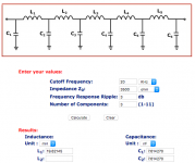
It makes sense from the component values point of view. However you've chosen 3dB ripple which I think is a bit of a bumpy ride for audio. Also this calculator assumes equal input and output impedances (you've entered 3500ohm) but in the case of a DAC filter the input impedance is very high (100s of kohm). So if you want to design your own DAC output filter with the passive I/V after the filter you'll find it unsuitable. But if you put the I/V resistor in parallel with C1 you'll do fine. Then you'll find you need 3500ohm on the output which gives too little voltage....
Btw I didn't mean to suggest by linking that LC calculator that it was going to give you a DAC filter like I designed for you. Its just as an example of LC filters.
Btw I didn't mean to suggest by linking that LC calculator that it was going to give you a DAC filter like I designed for you. Its just as an example of LC filters.
Last edited:
It makes sense from the component values point of view. However you've chosen 3dB ripple which I think is a bit of a bumpy ride for audio. Also this calculator assumes equal input and output impedances (you've entered 3500ohm) but in the case of a DAC filter the input impedance is very high (100s of kohm). So if you want to design your own DAC output filter with the passive I/V after the filter you'll find it unsuitable. But if you put the I/V resistor in parallel with C1 you'll do fine. Then you'll find you need 3500ohm on the output which gives too little voltage....
Btw I didn't mean to suggest by linking that LC calculator that it was going to give you a DAC filter like I designed for you. Its just as an example of LC filters.

I need to go have some more reading. I don't understand what ripple means in the filter (I used -3dB as seen somehwere else) and where those other numbers come from (ie I thought TDA1387 single chip SE was outputting 3.5Kohm, not 100s of Kohm).
Sorry, obviously my fault / lack of knowledge, you're being very patient.
I conceived of this back in September, got the boards made, but that J327 MOSFET has been out of stock forever. Another friendly forum member found some and ordered a bulk batch, and gave me some.
A big thanks to Matt - I got my RPi DAC HAT v1.6 board yesterday for free! Busy ordering the BOM.
 J327 is still out of stock at Mouser. Looks like DigiKey might still have. Is there an alternative?
False alarm - thank goodness, Mouser now reports "9,570 Can Ship Immediately". They must have updated their stock levels a few hours or minutes ago.
Oh, I was going to suggest a slightly better (electrically) alternative : SSM3J56MFV,L3F Toshiba | Mouser
This is my favourite I/V MOSFET right now. Its only downside is the package - its utterly minute, just 1.2mm for its longest dimension.
This is my favourite I/V MOSFET right now. Its only downside is the package - its utterly minute, just 1.2mm for its longest dimension.
Sorry folks, I made a mistake – Mouser is still out of stock for J327.False alarm - thank goodness, Mouser now reports "9,570 Can Ship Immediately". They must have updated their stock levels a few hours or minutes ago.
Abraxalito suggested SSM3J56MFV as an alternative, but Matt just said we must make sure it can work with 2.5v for its base voltage ("BREF"), specifically for the RPi HAT v1.6 board. This is not confirmed yet.
The 'base' (actually gate) voltage of 2.5V for J327 will work just as well for J56. A quick look at the DS shows the maximum Vth for both is -1V @1mA. Good luck with the soldering if you take the leap for J56 - remember to order the MFV package - the other one is even more of a nightmare to solder.
Looks like Mouser has the 327's back in stock:
Fantastic news. Thank you for the heads-up pcgab! Ironically I received most of my components today from Mouser via a local agent, including the replacement J56's.
they are super tiny. I can probably TRY to solder them using a friend's microscope but the main problem is the solder pads on the pcb are too spaced out for those tiny legs. I think I will rather order the J327's and wait a little longer.What I do with the J56s is solder one (or perhaps two) legs onto the pads. Then bridge the second (and/or third) pin with a 0ohm 0603 resistor to the PCB. Depending on layout the resistor could be to the gate terminal in which case can be the gate stopper R (I use 330R to 470R).
Much too quiet around here.
Matt, on the HAT DAC v1.6 BOM there are alternatives (MELF) for R4, R9. When to use the alternatives or shall I stick with the originals? I ordered both (2k7 and 1k1).
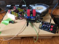
Started with stuffing my board, only to discover I slipped up ordering R12 and R13.
Matt, on the HAT DAC v1.6 BOM there are alternatives (MELF) for R4, R9. When to use the alternatives or shall I stick with the originals? I ordered both (2k7 and 1k1).
Started with stuffing my board, only to discover I slipped up ordering R12 and R13.
Much too quiet around here.
Indeed, though I'm much to blame on that front. Another big hobby of mine (guitar playing) just came out of a too-long hiatus. No room left in the "real life" part of the time budget to take for guitar, and the "hobby" slice isn't too big to begin with, and now it's heavily biased towards getting my playing back to a non-embarassing state. I'm thinking my next diyAudio project(s) will likely be for guitar, either effect pedals or tube amps. But I'll still check in here, for sure, so not going away!
Matt, on the HAT DAC v1.6 BOM there are alternatives (MELF) for R4, R9. When to use the alternatives or shall I stick with the originals? I ordered both (2k7 and 1k1).
Those are the I/V resistors. You probably want to use decent tolerance or hand-match the values, just so the left and right channels are balanced. But after that, it's more about taste, or more specifically, output power and impedance matching.
MELF resistors generally have ultra high tolerance, but they aren't necessary unless you're going for more of a "premium" build. (Well, those megabuck metal foil resistors would be the ultra-premium parts.)
The actual resistance value can also be adjusted to taste: the higher the value, the higher the output. Likewise, the lower the value, the lower the output. IIRC, 3.5k is the highest you can go given the tda1387's voltage compliance (at datasheet 5v supply anyway; if you overvolt the chip like Abraxalito likes to do, you can squeeze a bit more juice out of it).
I personally tend to use the lower values (around 1k) just because I have very modest power needs, and the lower values are simply a practical matter of giving me a more usable volume range (since I'm not using a pre-amp or active buffer).
Started with stuffing my board, only to discover I slipped up ordering R12 and R13.
It's not a real project until it can't be finished due to missing one boring part that you thought you had on hand or forgot to order! At least that's what I tell myself, since it seems to happen on, oh, 90% of my projects!
Enjoy the build, let me know if you have any more questions! If you go too long without a response, feel free to PM me, that will trigger an email.
Ok, thanks – I will try the original values first. I will be feeding a Aksa Lender preamp.I personally tend to use the lower values (around 1k) just because I have very modest power needs, and the lower values are simply a practical matter of giving me a more usable volume range (since I'm not using a pre-amp or active buffer).
Interesting. What are the advantages of overvolting the TDA1387 – i.e. squeezing more juice out of it – are there SQ benefits? And what voltage would the limit be?The actual resistance value can also be adjusted to taste: the higher the value, the higher the output. Likewise, the lower the value, the lower the output. IIRC, 3.5k is the highest you can go given the tda1387's voltage compliance (at datasheet 5v supply anyway; if you overvolt the chip like Abraxalito likes to do, you can squeeze a bit more juice out of it).
Yes, I feel/experience the same. Apart from two resistors I also short some hardware stuff – things you “think” are in your parts bin, like on/off switches, output sockets, etc. Only to find you’ve used the last ones on the previous project.It's not a real project until it can't be finished due to missing one boring part that you thought you had on hand or forgot to order! At least that's what I tell myself, since it seems to happen on, oh, 90% of my projects!
Great to see you are also coming on board Stellar.
I don't call a 6V supply for the TDA1387 'overvolting' myself, its right up against the absolute maximum but not beyond it. The advantage for me is it gives the possibility to go up to 4.5V on the DAC's output pins giving more flexibility for the I/V circuitry. The 20% extra current comes in handy too. I wouldn't say it sounds better though. Some other DIYers have gone beyond 6V...
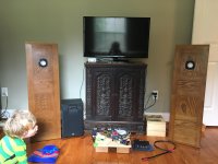
I have worked hard to make my RPi a quality I2S streamer, and auditioned many different DAC hats along the way. For a while I thought my favorite DAC might be the Audiophonics 1387 board. Nope. Once I got these simple DIY speakers set up for optimal imaging in my new listening room yesterday, there was no contest. Matt's RPi DAC v1.2 just beats everything else I have tried for realism. I would describe it as a sense of perfect focus. Approved by my 2-year-old son, too. I need to get in gear and build v1.6!
I need to get in gear and build v1.6!Attachments
- Home
- Source & Line
- Digital Line Level
- tda1387 dac pcb "front end"