So you'll be running it in master mode but using s/pdif? Are you sure that that is a valid configuration?
Nope, I meant to communicate the opposite. Because I'll be using SPDIF primarily (the inclusion of an I2S and DSD header are a nicety) I don't know if I need any of the clocking functions. As you imply there is no way to back clock SPIDF but I'm not sure if the ES9038 would still need me to set the NCO to match FSR*128 or something.
Brian
If all you'll be doing is feeding it s/pdif, the simplest thing you can do is to supply a fixed MCLK of at least 24.576MHz. But since we are living in a real world, just put in a fast oscillator with the lowest phase noise you can find. 80MHz to 100MHz is best. This way the ASRC will do a better job of de-jittering the signal.
You do not need to do anything with the NCO etc. Those settings are for when you are running the 9038 in master mode with an I2S slave.
You do not need to do anything with the NCO etc. Those settings are for when you are running the 9038 in master mode with an I2S slave.
If all you'll be doing is feeding it s/pdif, the simplest thing you can do is to supply a fixed MCLK of at least 24.576MHz. But since we are living in a real world, just put in a fast oscillator with the lowest phase noise you can find. 80MHz to 100MHz is best. This way the ASRC will do a better job of de-jittering the signal.
You do not need to do anything with the NCO etc. Those settings are for when you are running the 9038 in master mode with an I2S slave.
Thanks!
Update:
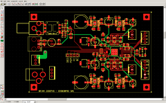
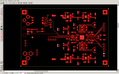
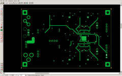
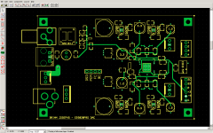
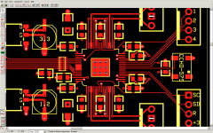
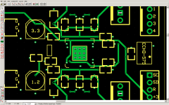
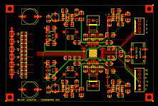
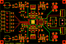
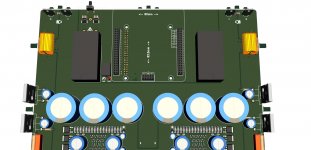
I've tightened up the layout a bit by switching to a smaller oscillator and splitting the digital signals into two headers. The lower left corner is reserved for input power conditioning. I still haven't worked out the power input just yet, whether to bring in a regulated 5V or include a regulator or DC-DC converter on board. Below are screen shots including some close ups of the ES9038 area.
I've tightened up the layout a bit by switching to a smaller oscillator and splitting the digital signals into two headers. The lower left corner is reserved for input power conditioning. I still haven't worked out the power input just yet, whether to bring in a regulated 5V or include a regulator or DC-DC converter on board. Below are screen shots including some close ups of the ES9038 area.
Attachments
-
 Screen Shot 2017-08-05 at 5.51.17 PM.png101 KB · Views: 1,116
 -
 Screen Shot 2017-08-05 at 5.51.26 PM.png72.8 KB · Views: 1,096
 -
 Screen Shot 2017-08-05 at 5.51.29 PM.png67.7 KB · Views: 1,065
 -
 Screen Shot 2017-08-05 at 5.51.32 PM.png89.2 KB · Views: 1,071
 -
 Screen Shot 2017-08-05 at 5.51.55 PM.png83.7 KB · Views: 1,074
 -
 Screen Shot 2017-08-05 at 5.52.05 PM.png76.5 KB · Views: 270
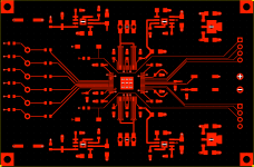
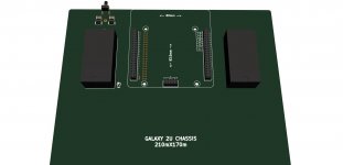
OK. I took a break because I was having trouble making decisions about what input formats and connectors to allow for. The board was packed and I wasn't sure I wanted build in the SPDIF conditioning at this stage since I'll be getting 3 boards and they may get 3 different I/O configurations. This new version is less packed and will have input connectors for (probably) 5 of the input pins so I can experiment with different formats. I'm leaning towards having pads for U.FL connectors and holes for terminal blocks. Still not done yet!
Are normal .1" headers "OK" for clock signals at high sample rates? I see them used on reputable boards.
I'm looking for recommendations on solid, low resistance headers or terminals to carry the signals to off-board I/V converters. The DAC want's to see 0 ohms in current mode.
Are normal .1" headers "OK" for clock signals at high sample rates? I see them used on reputable boards.
I'm looking for recommendations on solid, low resistance headers or terminals to carry the signals to off-board I/V converters. The DAC want's to see 0 ohms in current mode.
Attachments
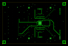
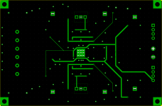
After doing some reading I've decided to go with a simple .2" pitch screw terminals on the input with enough connections for 3 SPDIF + 2 channels of either DSD or I2S. There will be a bottom plane pour over the whole board to help sink heat off the regulators but I have it hidden for now for clarity.
Attachments
I've signed the NDA for the datasheets a few days ago and hopefully look them over this week when/if I get them. I hadn't asked about it, but I would presume that it's possible to arrange the ability to collaborate if we formed something formal. Personally, I am at the point in my project that would benefit from a few upgrades and invite any level of collaboration. One way or the other it will get done in some form. I'll post my ideas later, perhaps starting a new thread.
S
S
I'll post my ideas later, perhaps starting a new thread.
Speaking of ideas, anyone think about asking people who have built a lot of these things in different variations and refinements what usually sounds best? Obviously, TP has been building ESS dacs a long time and is by now pretty far past fiddling around with 1st iteration designs. Also, Terry Demol seems to have built some custom ESS dacs for people who want the best SQ possible. He seems to know what usually works and what doesn't. By now, a lot is known about how to do it, and you may even get some valuable advice for free. OTOH, starting off thinking/guessing about 'this and that approach might be good,' is usually a quick road to mediocrity (if that). BTW, data sheets are necessary, but very sparse. They will not give much info about how to make a good sounding dac. However, if good SQ is a secondary concern, and the fun of doing it all one's own way is the real goal then please disregard all the foregoing.
")
Sounds wonderful
I've been asking around a little bit and haven't had much success or responses. My hopes are to get a platform ironed out to make it easier for DACs to be used with the Pi. My amp and DAC currently is all under one hood, controlling the amp as well, and can serve double duty as a standalone DAC as well in a smaller chassis. I have every intention to use smps and provide my own UPS for filesafe power cycling and such towards the project. It's pretty much down to the DAC at this point. Thanks for the leads, I'd be interested in even paying for services if need be. It's the final piece for my current system. I'll post some images later when I get a chance
S
Personally, I am waiting for the AK4499 evaluation boards to come out. Word has it they are intended to be AKM's all-out effort to take back market share from ESS. People who have heard the new dac say it sounds a lot better than Sabre. Of course, don't know what Sabre designs they have heard. Hopefully, something better than Oppo. In another month or two, maybe less, the boards should start appearing at suppliers such as Digikey.
Could be perfect timing
I gotta hit the sack, but take a look at the images attached.
One shows my amp system (Pi underneath)
another shows how it can function as a standalone DAC without the amp circuits
the last image shows my basic DAC
Essentially forming a base from which to focus on building DACs, as opposed to so many systems that look like piles of PCBs and balls of yarn.
This would include my UPS as well that babysits and delivers the right power to the Pi
S
Attachments
It has been a while since any update, is it still a work in progress ?
Unfortunately, I was given some advice that my grounding scheme was not likely to work. I had found som ESS literature that stated using one common ground for all digital and analog paths performed best. It was suggested to me that this applied to older DAC chips from Sabre and that the 9038 pulled so much current that this may not be advisable. I lost my stride after that and haven’t thought once about building a DAC. I still have a pair of chips though - perhaps someone here can post some of their work and re-inspire me?
Brian
I'm certainly willing to collaborate and share with anyone else willing the same. I suppose I'm not necessarily looking to reinvent the wheel here, but more create a stable foundation to build from. There appear to be many iterations and variations, I just know for myself that there's a middle ground that I'm aiming at that will over time get better and better. In other words, I'm not looking for be all end all, I'm looking for good enough to get better and better, and willing to work with others and share my work as well. I'm close to providing the foundation for such and will start a new thread soon. Perhaps the AK4499 could be a great beginning for such. My preliminary requirements are minimum differential 2ch outs, hardware volume, hardware mute. Yet to be seen on the tech specs, so.. Everything is nearly done except for the details in how the DAC will work and be with the system, so for me, all that time will be focused on this DAC project.
ESS touts their flawless ASRC, six built-in PCM filter choices, etc. Most people who try everything the chips can do find synchronously clocked DSD over galvanically isolated USB, and with reclocking following isolation stage to sound best. Of course, it depends on the quality of the DSD to start with, and HQplayer is probably the most popular converter for its good SQ.
The cheapest really good isolated USB board with native DSD support, ASIO drivers, etc., is made in Bulgaria. I2SoverUSB - I2S over USB Audio
It can accept as clock inputs your clocks from the dac board so as to keep USB synchronous with the dac clock. It can work with ESS or AKM dacs. It can provide a signal to tell you which clock to select for the master synchronous clock (44.1 family of sample rates, or 48 family).
That's probably the best diy way to get great dac sound quality, if SPDIF is not a requirement. Of course, lots of voltage regulators are needed to keep different circuit functions operating cleanly. Analog and digital circuits have different voltage regulator needs. Sensible and proven output stage designs are most likely to work well, probably better to avoid this or that other circuit, until after you have heard the properly implemented recommended circuits. That means OPA1612 for IV stages. Depending on where output signals go from there, some options start to appear. Proper grounding is crucial for best performance and sound quality, of course. Excellent isolation from power line noise can also have very significant results.
Last edited:
After doing some reading I've decided to go with a simple .2" pitch screw terminals on the input with enough connections for 3 SPDIF + 2 channels of either DSD or I2S. There will be a bottom plane pour over the whole board to help sink heat off the regulators but I have it hidden for now for clarity.
Maybe making some room for NZ2520SDA cyrstal?
It's smaller, less-expensive and even as good as CCHD-957s.
- Status
- This old topic is closed. If you want to reopen this topic, contact a moderator using the "Report Post" button.
- Home
- Source & Line
- Digital Line Level
- DIY ES9038pro Board