Before I go through the time consuming process of making a schematic symbol and a footprint, I thought I'd ask if anyone has made those for this board:
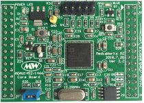
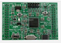
ADAU1452 Core Board
It has the same dimensions and pinouts as the AD1466 Core Board
I just finished making it.
That has to be the most boring part of PCB design, making symbols and footprints. I made it in KiCad's nightly version, 5.99.
Attachments
Hi Mayday
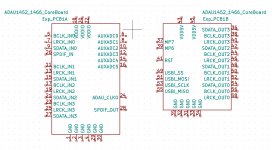
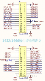
This is the schematic and elements I have on hand for the "ADAU1452 mediaworks core board" ... hope this is what you are looking for !
This is the schematic and elements I have on hand for the "ADAU1452 mediaworks core board" ... hope this is what you are looking for !
Attachments
Thanks!Hi Mayday
This is the schematic and elements I have on hand for the "ADAU1452 mediaworks core board" ... hope this is what you are looking for !
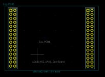
I didn't have the schematics, but I found the dimensions and pinout info for the 2x 30pin headers (this is what I used to make the schematic symbol and PCB footprint).
I'm considering making myself a "motherboard" for one of those Core Boards as they call them.
Sigma Studio
I'm decent at designing PCB's, but I'm not really that familiar with Sigma Studio.
My idea for this "motherboard" is to have I²S input(s) and SPDIF input(s) and I²S output plus SPDIF output.
I'm also considering having low noise LDO's, with the option of not populating the parts for those(with bypass jumpers) to allow for Super regulators etc.
This will of course require minor modifications to the ADAU1452 Core Board.
If anyone familiar with the ADAU1452 (Core Board) is willing to help with what pins to route I²S, SPDIF in and out that would be greatly appreciated.
Not looking to sell any boards, if the result is good enough I'll post the gerbers and schematic as open source.
I'm looking at this as I don't want any extra A/D-conversion in the signal path.
I think it's good to have options for what D/A-converter to use after the ASRC/DSP.
I don't think I'm alone in that.
Hi Mayday,
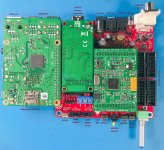
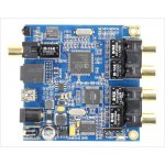
IDK what you need as I know nothing of PCB design. I do have an ADAU 1452 with SPDIF input and output, composed of the main board and AD1938 CODEC.
I have a few diagrams sent to me by the seller, hope it helps.
Also, as you are decent making PCBs... is it possible to have an ADAU 1452 with HDMI input (8 channel PCM audio)? HDMI to I2S to ADAU1452, to keep sound in the digital domain.
SigmaStudio is very easy to start and have the basics working (I know I have and I am not an engineer), but it can get really really advanced if you want. It's a really powerful tool, constantly updated with great support at AD EngeneerZone.
Cheers.
Attachments
Last edited:
Hi Mayday,
IDK what you need as I know nothing of PCB design. I do have an ADAU 1452 with SPDIF input and output, composed of the main board and AD1938 CODEC.
I have a few diagrams sent to me by the seller, hope it helps.
Also, as you are decent making PCBs... is it possible to have an ADAU 1452 with HDMI input (8 channel PCM audio)? HDMI to I2S to ADAU1452, to keep sound in the digital domain.
SigmaStudio is very easy to start and have the basics working (I know I have and I am not an engineer), but it can get really really advanced if you want. It's a really powerful tool, constantly updated with great support at AD EngeneerZone.
Cheers.
I'll answer later, I have my 4 year old daughter with me now.
Member
Joined 2018
FYI:MW-ADAU1466 DSP Pre Design
Hello Mayday-San,
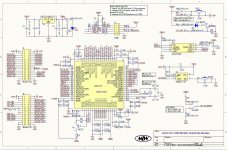
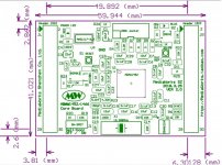
Maybe you can see some ideas in my board design...
(Sorry! written in Japanese)
DIY DSP PRE-AMP PROJECT PAGE
(Machine Translation)
Google Translate
CyberPit
Hello Mayday-San,
Maybe you can see some ideas in my board design...
(Sorry! written in Japanese)
DIY DSP PRE-AMP PROJECT PAGE
(Machine Translation)
Google Translate
CyberPit
Attachments
Thank you!Hello Mayday-San,
Maybe you can see some ideas in my board design...
(Sorry! written in Japanese)
DIY DSP PRE-AMP PROJECT PAGE
(Machine Translation)
Google Translate
CyberPit
I will have a look at what you have done more closely later, but first impression is that you have designed a very nice PCB.
Hi Mayday,
IDK what you need as I know nothing of PCB design. I do have an ADAU 1452 with SPDIF input and output, composed of the main board and AD1938 CODEC.
I have a few diagrams sent to me by the seller, hope it helps.
Also, as you are decent making PCBs... is it possible to have an ADAU 1452 with HDMI input (8 channel PCM audio)? HDMI to I2S to ADAU1452, to keep sound in the digital domain.
SigmaStudio is very easy to start and have the basics working (I know I have and I am not an engineer), but it can get really really advanced if you want. It's a really powerful tool, constantly updated with great support at AD EngeneerZone.
Cheers.
I've only done DIY in stereo, I have no knowledge of how create a schematic that works as you describe the HDMI feature you want.
If someone else did the schematic for that part, I can do the layout.
My main goals are to keep the audio in and out from the ASRC/DSP digital, so that I can choose what D/A-converter(s) to use and avoid the A/D-conversion.
Cheers.
Hello Mayday-San,
Maybe you can see some ideas in my board design...
(Sorry! written in Japanese)
DIY DSP PRE-AMP PROJECT PAGE
(Machine Translation)
Google Translate
CyberPit
Having looked a bit closer at the schematic and board, I have to compliment you on a very nice design.
Mine will be a little different, I wish to have SPDIF in and out via U.FL connector.
I'll also use those connectors for I²S in and out.
Not being very familiar with the ADAU1452/ADAU1466, are the buffers (logic) necessary for I²S out?
If not, I'd like to know the reason you chose to use them.
I like the options for input in your design.
Not sure I can implement your source select part of the schematic (given that you are ok with that in the first place).
My inputs would be USB(via XMOS208 with Sitime oscillators), if I don't just use the SPDIF out from that board. I will also have I²S input. I don't think I will have any analog inputs, I haven't made up my mind about that but I don't think I'll use analog in.
Thank you for sharing your work!
Best regards
Maybe use transformers like miniDSP-nanoDIGI on inputs-outputs?
Mine is dead quiet at output and I think transformers do some of the work.
Yes I plan on using Murata DA101C or Pulse PE65612.
@Mayday:
That ADAU1452 dsp board costs about 44 $ on ebay.
ADAU1452 dsp chip is ~12 $ on mouser.
So how did you came up with the idea to design an interface-add-on-board for that dsp board from china (china engineering "quality" included)?
Seems to be non-sense to me. Just layout a dsp board with adau1452 and the needed interface directly on one pcb. Digital audio chips like sigma dsp's are really easy to handle.
@Mayday:
That ADAU1452 dsp board costs about 44 $ on ebay.
ADAU1452 dsp chip is ~12 $ on mouser.
So how did you came up with the idea to design an interface-add-on-board for that dsp board from china (china engineering "quality" included)?
Seems to be non-sense to me. Just layout a dsp board with adau1452 and the needed interface directly on one pcb. Digital audio chips like sigma dsp's are really easy to handle.
I figured I would try this first.
Mainly due to a lack of time to design the ADAU1452/1466 circuitry in the foreseeable future.
It may seem like non-sense to you, but that is the beauty of opinions, everyone is entitled to their own.
Member
Joined 2018
About the I2S output buffer
Mayday-San,
I'm glad to hear from you. Would be the help is my pleasure.
The reason why I had add the Tri-State Buffers on each I2S output Headers, there are two reasons. Mainly depend on a signal integrity at the DAC's input pins.
Reason1:
Considering fan-out (Load) effect on the MCLK line. Driving four I2S connection ribbon cables at 24.576MHz directly seems to be a heavy load for ADAU1452/1466.
Reason2:
Wanted to do the same output impedance/dumping factor the rest of I2S signal lines. But this part might not necessary, because the fan-out is 1 and the signal frequency is not so high.(I'm Not sure for all cases)
I implement additional option output-enable control, if the output buffer is not necessary for the user's application. It will reduce the power consumption and the emitting Noises.
Best Regards,
CyberPit
Mayday-San,
I'm glad to hear from you. Would be the help is my pleasure.
Not being very familiar with the ADAU1452/ADAU1466, are the buffers (logic) necessary for I²S out?
If not, I'd like to know the reason you chose to use them.
The reason why I had add the Tri-State Buffers on each I2S output Headers, there are two reasons. Mainly depend on a signal integrity at the DAC's input pins.
Reason1:
Considering fan-out (Load) effect on the MCLK line. Driving four I2S connection ribbon cables at 24.576MHz directly seems to be a heavy load for ADAU1452/1466.
Reason2:
Wanted to do the same output impedance/dumping factor the rest of I2S signal lines. But this part might not necessary, because the fan-out is 1 and the signal frequency is not so high.(I'm Not sure for all cases)
I implement additional option output-enable control, if the output buffer is not necessary for the user's application. It will reduce the power consumption and the emitting Noises.
Best Regards,
CyberPit
Hi,Mayday-San,
I'm glad to hear from you. Would be the help is my pleasure.
The reason why I had add the Tri-State Buffers on each I2S output Headers, there are two reasons. Mainly depend on a signal integrity at the DAC's input pins.
Reason1:
Considering fan-out (Load) effect on the MCLK line. Driving four I2S connection ribbon cables at 24.576MHz directly seems to be a heavy load for ADAU1452/1466.
Reason2:
Wanted to do the same output impedance/dumping factor the rest of I2S signal lines. But this part might not necessary, because the fan-out is 1 and the signal frequency is not so high.(I'm Not sure for all cases)
I implement additional option output-enable control, if the output buffer is not necessary for the user's application. It will reduce the power consumption and the emitting Noises.
Best Regards,
CyberPit
After having looked at your schematic I understand why you have the buffers.
Again, it's a very nicely designed board.
I'm not going to have any analog inputs in my design, and I'll use coax/BNC for SPDIF.
For I²S in and out, I'm leaning heavily toward using U.FL connectors. This will get a shielded in/out without taking up alot of board-space.
I may de-solder the Core Board 12.288MHz oscillator and use a better oscillator, maybe as a small add-on board.
My goals are, one I²S input, one USB input (XMOS 208 or Amanero) and one SPDIF input via coax or, preferably, BNC.
The onboard connectors for all(except XMOS/Amanero) will be U.FL.
BNC or Coax will be chassis mounted.
I got a bunch of U.FL to U.FL cables and U.FL to un-terminated cables.
How critical is the precision of the resistors on the in and out of the buffers?
If not too critical, I'll save board-space using resistor-networks (small footprint parallel resistors in this case).
My biggest hurdle is Sigma Studio. I'm a novice at best.
Again, my compliments on a well designed board.
It's drag and drop very easy when you got the hang of it.My biggest hurdle is Sigma Studio. I'm a novice at best.
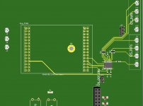
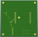
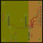
I've started a preliminary layout. From past experience it'll change a number of times before I'm happy with it.
All I've done is take the I2S, via SN74HCT541(Thank you CyberPit-san), to U.FL connectors.
I've placed Murata DA101C digital transformers for SPDIF in/out and a pinsocket for Amanero/XMOS208(w sitime oscillators, I have one of those at home).
This just a rough starting point and will most likely change alot before I send anything of to a boardhouse.
Board size is currently 120x120mm
I know there are spelling errors etc on the board. Remember, this is like 5-10 versions from what I'd consider an Alpha-release.
Attachments
Last edited:
It's drag and drop very easy when you got the hang of it.
That may be true, I haven't had the time or fokus to really dive in to Sigma Studio.
- Home
- Source & Line
- Digital Line Level
- low cost ADAU1452 China board...