Member
Joined 2018
Hi Mayday-San,3. I have a measuring mic built according to Linkwitz site, including a OPA2134 mic amp. But I am thinking of getting a UMIK-1.
The positioning of my speakers is far from ideal and I'm sure SQ will be significantly improved with room correction via REW and SigmaStudio.
I have never done that however, and have no clue how to implement the output from REW in SigmaStudio.
You can export measured response and phase data in MLSSA format then import to SigmaStudio AutoEQ crossover.
Following my web-page will help to understand some...
(Machine translation version)
Google 翻訳
(Original Japanese version)
DIY DSP PROCESSOR PROJECT PAGE
Last edited:
There is absolutely no way to brick this board, short of using a 12V programmerOk.
I suppose it'll be a little trial and error to see what works on my board. Can't really brick it unless I really screw up I guess. In that case I have two working ADAU1701 boards to fall back on.
I still have a lot to learn about how to configure the setup in SigmaStudio and, at some point, using REW to measure the room, make corrections and then implementing that in SigmaStudio.
") . Unlike standard processors which need a bootloader that can be flashed (and if corrupted brick it), the ADAU1452 flashing only loads a series of parameters in memory. Power off, and it's back to where it was
. Unlike standard processors which need a bootloader that can be flashed (and if corrupted brick it), the ADAU1452 flashing only loads a series of parameters in memory. Power off, and it's back to where it wasKeep in mind that in my case, I need to use SPI to program the ADAU1452, and if I want to program the EEPROM, I need to program it using the "write latest compilation through DSP" option. It's all explained in one of the documents provided with the board (and shared here previously as a ZIP file). I took the time to translate the instruction document from Chinese, enclosing it here.
Attachments
Hi Mayday-San,
You can export measured response and phase data in MLSSA format then import to SigmaStudio AutoEQ crossover.
Following my web-page will help to understand some...
(Machine translation version)
Google 翻訳
(Original Japanese version)
DIY DSP PROCESSOR PROJECT PAGE
Thank you CyberPit-san!
Thank you robca!There is absolutely no way to brick this board, short of using a 12V programmer
Keep in mind that in my case, I need to use SPI to program the ADAU1452, and if I want to program the EEPROM, I need to program it using the "write latest compilation through DSP" option. It's all explained in one of the documents provided with the board (and shared here previously as a ZIP file). I took the time to translate the instruction document from Chinese, enclosing it here.
Suggestions for a common earth point.
Good day to you all,
I am working with an ADAU_1542_DSP and AD_1938_CODEC board.Programming with I2C works well. I have been able to make some adjustments to the "original configuration" of "ADAU1452_192tdm/I2C.dspproj".I found a lot of help for this in this forum. Unfortunately, I don't know Chinese. But bit by bit you can understand the programming.
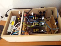
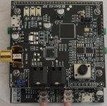
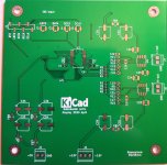
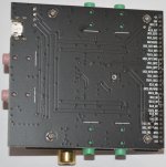
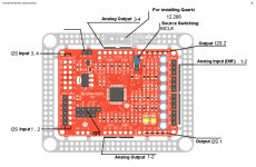
I've captured my setup in the picture.
1 Left tweeter/midrange (Wondom TAMP2100)
2 Right tweeter/midrange (Wondom TAMP2100)
1 SUB Left/Right (Wondom TAMP2100)
4 Loudspeaker protection (DC and plops) 2x3 relay channels optocoupler
5 Voltage/current 2 Meanwell EPP-150-27, 1 No Name power supply 24V 10A (for SUB).
6 Power supply for preamplifiers (DSP, speaker protection, 6 channel volume control etc.). Talema transformer 2x9V 25VA
7 ADAU_1542 board
Cable for signal transmission not connected in the picture.
I soldered the power supply for the DSP from the transformer (rectifier/capacitor) via a StepUpConverter to pins 1 (5V) and 2 (GND). The voltage for the loudspeaker protection comes from the second winding. Also unregulated via rectifier/capacitor. The protection circuit has a 7912 regulator. The volume control would be supplied with 2x9V symmetrical AC voltage.
Can I do it this way, or should I rather use a USB port to supply the DSP? And if so, which of the two?
And now comes my problem: I have a slight noise. Really very quiet. A slight analogue noise would be normal for me. This is to be controlled by a 6 channel volume control with PGS2311 before the power amplifiers.
But very quietly in the background I have a beeping. Maybe 1 Khz. I'll have to try the oscilloscope.
Do you have any suggestions for the wiring of the grounding? The power supply units and the power amplifiers are connected to a common ground point on the protective earth.
Good day to you all,
I am working with an ADAU_1542_DSP and AD_1938_CODEC board.Programming with I2C works well. I have been able to make some adjustments to the "original configuration" of "ADAU1452_192tdm/I2C.dspproj".I found a lot of help for this in this forum. Unfortunately, I don't know Chinese. But bit by bit you can understand the programming.
I've captured my setup in the picture.
1 Left tweeter/midrange (Wondom TAMP2100)
2 Right tweeter/midrange (Wondom TAMP2100)
1 SUB Left/Right (Wondom TAMP2100)
4 Loudspeaker protection (DC and plops) 2x3 relay channels optocoupler
5 Voltage/current 2 Meanwell EPP-150-27, 1 No Name power supply 24V 10A (for SUB).
6 Power supply for preamplifiers (DSP, speaker protection, 6 channel volume control etc.). Talema transformer 2x9V 25VA
7 ADAU_1542 board
Cable for signal transmission not connected in the picture.
I soldered the power supply for the DSP from the transformer (rectifier/capacitor) via a StepUpConverter to pins 1 (5V) and 2 (GND). The voltage for the loudspeaker protection comes from the second winding. Also unregulated via rectifier/capacitor. The protection circuit has a 7912 regulator. The volume control would be supplied with 2x9V symmetrical AC voltage.
Can I do it this way, or should I rather use a USB port to supply the DSP? And if so, which of the two?
And now comes my problem: I have a slight noise. Really very quiet. A slight analogue noise would be normal for me. This is to be controlled by a 6 channel volume control with PGS2311 before the power amplifiers.
But very quietly in the background I have a beeping. Maybe 1 Khz. I'll have to try the oscilloscope.
Do you have any suggestions for the wiring of the grounding? The power supply units and the power amplifiers are connected to a common ground point on the protective earth.
Attachments
Last edited:
@blubbervill, 3 things come immediately to mind, in order of relevance
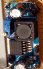
- The step up module you use is known to be horrible quality. Use a high quality 5V power supply with minimal ripple
- You have too many analog and digital boards and components into a too small enclosure with no visible shielding. Think of having the DSP inside a metallic cage (with good ventilation, that board can get really hot)
- Even after all of this, a very faint noise is inevitable with a cheap board like this. The analog portion (AD1938) is designed for low cost, not high quality and minimal noise
For me it sound really good... but its only subjective...
Someone with the proper insturments could measure the ADC performance and DAC. Spec wise they are respectable.
Specs of the chips are respectable. Actual performance in this type of board is actually notably worse. Designing low noise circuits is very hard. In this case, designing a board that can be used at different clock speeds, would require optimizing input and output filters for each frequency (which is not possible in our case)
The actual performance depends on which input you use (in my case some inputs are noisier than others), the clock frequency used, input and output device impedance, power supply, additional filtering, etc. And I'm willing to bet really good money that every individual board behaves slightly differently, due to the cheap components used with different components tolerances
Put it another way, you will need to measure your specific case once you define everything else around it.
I would not use this board (the AD1938 portion, I mean) to build truly high quality audio devices. This is a great board to play with and learn, then use the ADAU1452 portion only and a really good ADC or DAC, optimized for your specific use. the ADAU1452 board, being 100% digital, will be able to work with much higher quality AD/DA components with no appreciable decrease of quality. Keep in mind that any DSP, by its nature, will never be measured as good as a highly optimized DAC, with precision clock, since the DSP engine itself will modify the digital signal by design and introduce measurable jitter. But, then again, i's what we need the DSP to do: modify the signal
Member
Joined 2018
And now comes my problem: I have a slight noise. Really very quiet. A slight analogue noise would be normal for me. This is to be controlled by a 6 channel volume control with PGS2311 before the power amplifiers.
But very quietly in the background I have a beeping. Maybe 1 Khz. I'll have to try the oscilloscope.
Do you have any suggestions for the wiring of the grounding? The power supply units and the power amplifiers are connected to a common ground point on the protective earth.
Are you electrically connect the each aluminum brace boards?
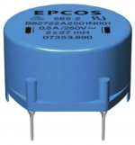
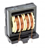
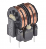
If the each boards are well designed, you can try to insert the huge common-mode chokes for each board's power supply cables.
Something like this...
Attachments
Specs of the chips are respectable. Actual performance in this type of board is actually notably worse. Designing low noise circuits is very hard. In this case, designing a board that can be used at different clock speeds, would require optimizing input and output filters for each frequency (which is not possible in our case)
The actual performance depends on which input you use (in my case some inputs are noisier than others), the clock frequency used, input and output device impedance, power supply, additional filtering, etc. And I'm willing to bet really good money that every individual board behaves slightly differently, due to the cheap components used with different components tolerances
Put it another way, you will need to measure your specific case once you define everything else around it.
I would not use this board (the AD1938 portion, I mean) to build truly high quality audio devices. This is a great board to play with and learn, then use the ADAU1452 portion only and a really good ADC or DAC, optimized for your specific use. the ADAU1452 board, being 100% digital, will be able to work with much higher quality AD/DA components with no appreciable decrease of quality. Keep in mind that any DSP, by its nature, will never be measured as good as a highly optimized DAC, with precision clock, since the DSP engine itself will modify the digital signal by design and introduce measurable jitter. But, then again, i's what we need the DSP to do: modify the signal
Have you measured the board?
Cheers
The aluminium plates on which the amplifiers are mounted are connected to the common earth point. I realise that everything is close together. But it is a test.
The amplifiers, i.e. the WONDOM TAMP2100 are very quiet without connecting cables at the input. But not completely.
I'm not designing the ultimate high-end system. But it really surprised me what quality can be achieved with the ADAU1542 and the CODEC board. Or rather with what I have put together.
The DSP and the DA-converters should always work at a high level for a good signal/noise ratio. That's why a volume control is planned in front of the power amp inputs. This could be done with PGS2311 or, if there is noise, with a relay.
I just wasn't sure where the DSP board is supplied with power. Solder the supply to pins, or use one of the two USB connections. But that doesn't seem to have any influence.
I just removed the two MeanWell EPP-150-27s from the installation. The cheap power supply is now the only power supply for the output stages. The quiet beeping is gone. Previously, I had connected a MeanWell power supply unit as the only power supply for the power amplifiers in the system. This resulted in distinct (loud) whistling. What I don't understand. (???)
Then I played with the power supply for the DSP board. LM317, LM2596 or now XL6009 makes no audible difference in terms of noise. Everything is minimal.
Yes, very quickly with my scope and signal generator. But even without measuring, it's pretty easy to hear the analog noise once you amplify enoughHave you measured the board?
Cheers
I have not taken complete measurements since I have not decided yet what sampling frequency I will use (very likely 96kHz)
And in any case I don't plan to use the analog inputs, which in my quick tests are the worst part of the board. As I mentioned, one of the analog inputs in my board is notably worse (don't remember anymore which one)
If there is any specific test you would like to see, I can try and find the time to do it. But, as usual, keep in mind that every board is likely to be slightly different due to the cheap components used
Last edited:
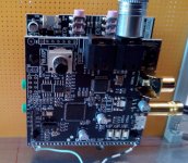
ADAU1452 w coax in and external DAC's?
I it possible to use my dual WM8740 boards(Or other) as outputs via I2S?
In essence use the coaxial (or I2S) in from an Audio-Widget(I2S only) or XMOS XU2008 board, do the signal processing and send the processed signal to external DAC's.
The ferrite bead footprints can be populated with inductors(between the power supply caps) for C-L-C filters.
The board is set for 24bit I2S, Dual Differential Hardware Setup accoring to fig.23 in the datasheet and it's using LT1028's on the output.
If these boards won't work, I have a couple of the cheap ES9023 boards with onboard oscillator, one ES9018Q2M board, three Red Baron V5 boards and two (I think) dual PCM1794 boards.
Ideally, I'd use a Red Baron V5(TDA1541A) for the output to the main speakers and another for the dipole subwoofer, or one of the ES9023 boards for the subwoofer.
BTW:
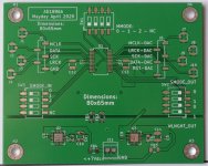
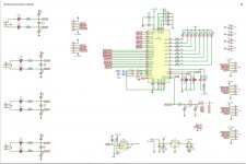
Does anyone have the drawing for the ADAU1452 board? The DSP board, with dimensions for mountingholes and the pins going down to the AD1938 board?
I it possible to use my dual WM8740 boards(Or other) as outputs via I2S?
In essence use the coaxial (or I2S) in from an Audio-Widget(I2S only) or XMOS XU2008 board, do the signal processing and send the processed signal to external DAC's.
The ferrite bead footprints can be populated with inductors(between the power supply caps) for C-L-C filters.
The board is set for 24bit I2S, Dual Differential Hardware Setup accoring to fig.23 in the datasheet and it's using LT1028's on the output.
If these boards won't work, I have a couple of the cheap ES9023 boards with onboard oscillator, one ES9018Q2M board, three Red Baron V5 boards and two (I think) dual PCM1794 boards.
Ideally, I'd use a Red Baron V5(TDA1541A) for the output to the main speakers and another for the dipole subwoofer, or one of the ES9023 boards for the subwoofer.
BTW:
Does anyone have the drawing for the ADAU1452 board? The DSP board, with dimensions for mountingholes and the pins going down to the AD1938 board?
Attachments
Last edited:
I it possible to use my dual WM8740 boards(Or other) as outputs via I2S?
In essence use the coaxial (or I2S) in from an Audio-Widget(I2S only) or XMOS XU2008 board, do the signal processing and send the processed signal to external DAC's.
The ferrite bead footprints can be populated with inductors(between the power supply caps) for C-L-C filters.
The board is set for 24bit I2S, Dual Differential Hardware Setup accoring to fig.23 in the datasheet and it's using LT1028's on the output.
If these boards won't work, I have a couple of the cheap ES9023 boards with onboard oscillator, one ES9018Q2M board, three Red Baron V5 boards and two (I think) dual PCM1794 boards.
Ideally, I'd use a Red Baron V5(TDA1541A) for the output to the main speakers and another for the dipole subwoofer, or one of the ES9023 boards for the subwoofer.
BTW:
Does anyone have the drawing for the ADAU1452 board? The DSP board, with dimensions for mountingholes and the pins going down to the AD1938 board?
The ADAU1452 itself only "speaks" I2S/TDM up to 192KHz, or SPDIF/AES up to 96KHz. The AD1939 board inputs send I2S to the ADAU, and the ADUA sends I2S to the AD1939 outputs. The jumpers on the AD1939 board set different types on I2S data streams (and uses either I2S or TDM depending on the clocks, you can look at one of my old posts with all the details)
So if you have data in I2S format that you want processed and D/A speaking I2S as outputs, all you have to do is to remove the AD1939 board, use the many I2S inputs and outputs on the ADAU1452 board and properly program all the input and output formats for I2S. The ADAU1452 is incredibly flexible in I2S formatting, plus has an ASRC engine that allows different formats/clock speeds to coexist. So it's hard to imagine having problems receiving or sending data to any I2S chip
Thanks
So...
The most flexible, option would be feeding the ADAU1452 I2S in(I'm not at all familiar with TDM tbh), and having it feed I2S out to D/A-converters.
Most flexible without becomming too complicated.
I would like to make a sort of replacement board for the AD1938, with a pinsocket for the ADAU1452 board, maybe add decent low noise powersupply/powersupplies for the DSP-board(if possible without too much modification to the board) and U.FL connectors plus Molex KK(or similar).
Sort of a breakout board for the pinheader of the DSP-board, possibly with better powersupply(the pcb space is there, as it would match the size of the AD1938 board more or less, why not use it).
I need help programming the AD1938 CODEC which I've got from chipdip.ru (by the way, tahnks drMorder!)
You se... I am trying to connect two AD1938 in "daisy chain" mode to one ADAU1452 DSP, but I am stuck...
The first thing I want to do is to config the hardware registers on both codecs so they can work in "daisy chain". For that I am using USBi and Sigma Studio (SPI).
USBi is properly connected and detected by Sigma Studio. I am using SPI, so MISO, MOSI, SS and SCL are used between USBi and AD1938. Also, 5volts are provided to the codec.
When I choose "Get Current Settings from Chip" all AD1938 settings go to default (all muted, disabled, power down, etc.). After that I modify all the settings and choose "Write Current Settings to Chip". Everything seems to be written to the chip, as my capture screen shows the blocks write, and "Downloaded" is shown on the right bottom corner. So far so good.
To verify that settings where written to codec, I now set "Get Current Settings from Chip" , which should show all the settings I made previously, but instead all goes -again- to default (all muted, disabled, power down, etc.).
I posted this on AD EngeneerZone and the thankful DaveThib offered me some insight, but I am still stuck and not being able to program the AD1938CODEC using SPI.
DaveThib suggest the SS pin on the codec needs to be a pull up resistor on it to keep the codec from going into standalone mode. I am not very technical, but that means that I have to connect the SS pin to 5volts output with a 10kOhm resistor, correct? I've tried this but got the same results.
Then found this page: Stand-alone Modes on the AD193x audio CODECs - Documents - Audio - EngineerZone
And I am not sure If I need to pull up the SS pin or COUT = MISO pin...
Also, he mentions that I need to "Hard Reset" the codec before trying the pullup resistor... that means just power cycle it, right?
I tried this with a chipdip.ru branded USBi which works OK, as I can write my scheme to DSP, etc.
Any clues what I am doing wrong?
Thanks
Attachments
Just to be sure that we are all on the same page (sorry, not meant to be patronizing, but it's always hard to know what another person knows about a specific device, so Iprefer making sure that I state the obvious to eliminate communication problems)
First of all, the AD1938 is a 3.3V chip only. That means that if you need a pull up, you need to pull up to 3.3V, not 5V. Using 5V on any pin has a very high risk of damaging the chip. Anything above 3.3Kohm resistor works as a pull up usually. (not your case but: if the pin is a pull up that also needs to be driven by another device, the resistor must be sized properly to ensure that you do not get above the driving pin specs and still have a small enough resistor value to pull up the pin quickly)
Second: just to double check: you are not trying to program the AD1938 and save the setting between power ups, right? the AD1938 has no memory, so it needs to be reprogrammed at every power up cycle. You will need a dedicated microprocessor to properly program the AD1938 at every power up, since using the USBi every time is not feasible (it's ok for development and to figure out the right registry values)
Third: if you want to program the AD1938, you do not want to use it in standalone mode. Standalone mode means that the chip is powered on with all settings as default, and nothing can be changed. The device in this thread uses a microprocessor on the AD1938 daughter board that programs the AD1938 at every power up with the settings, based on the jumper position
So, for a moment let's forget about daisy chain and focus on having a single AD1938 connect to the DSP. Look for my posts here and you will find a description of how the AD1938 on the Lusya board is programmed for each configuration, and try to replicate it and see if i works. The AD1938 and ADAU1452 must be programmed properly for the two to communicate. Once again, using the AD1938 settings on the Lusya board and the example projects for the ADAU1452 you should be able to have a single AD1938 work with the ADAU1452
Last edited:
- Home
- Source & Line
- Digital Line Level
- low cost ADAU1452 China board...