Marcel, I am planning to use my audio analyser (RTX6001 with Multi Instrument Pro full license) to measure some basic parameters of my ValveDac. So far I've only used it to measure the complex input impedance of my monobloc 6 channel SET amps that use passive line level crossovers, so I will be learning along the way. All kinds of things could be quantified.
My thinking is that it may be a useful for perhaps seeing the effects of different reconstruction filters and power supply arrangements and no doubt several other things as well. Is this something suitable for this thread?
Anthony
My thinking is that it may be a useful for perhaps seeing the effects of different reconstruction filters and power supply arrangements and no doubt several other things as well. Is this something suitable for this thread?
Anthony
Yes, of course. I'm particularly interested in what A-weighted noise floor you get after trimming.
I took my measurements with a HAMEG analogue scope with cursors (frequency response, coarse out-of-band noise measurements) and with a Fostex FR2-LE field memory recorder and the GoldWave digital audio editing program (A-weighted noise, harmonic distortion). Worked surprisingly well, considering that neither a field memory recorder nor an audio editor are meant for doing measurements.
I also have an old BKF6d valve distortion meter, but I was afraid it wouldn't be able to deal with the out-of-band noise of a sigma-delta DAC.
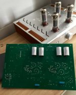
I’m a bit late due to so many other projects needed to clear out... Just got the tube voltage regulator up and running this morning. Output voltage is very stable at +300V. I need to do some modifications to get it right at -300V, should be easy.
The DAC board still misses a lot of small caps though. I’m still waiting for a suitable hardware solution for pcm-dsd conversion, don’t want to go through the HQPlayer path.
The DAC board still misses a lot of small caps though. I’m still waiting for a suitable hardware solution for pcm-dsd conversion, don’t want to go through the HQPlayer path.
Attachments
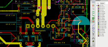
Because of a private question I got, I post a picture of connector T6, the one that's drawn as a transformer on the schematic. Pins 1 and 2 are for the 230 V AC that is used to generate the -300 V (not applicable when you have an alternative -300 V supply), pins 3 and 4 are for the 6.3 V for the heaters and pins 5 and 6 for the 6.3 V AC from which the 5 V is derived. The picture is for the raw DSD version, but it is very similar in the original valve DAC.
Attachments
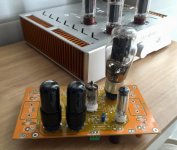
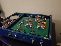
Finally got my case in and the bottom panel had an error lol. The shop is remaking it. I assembled the ValveDAC anyway but didn't zip tie wires or anything.
It sounds amazing, no pops at all. Only issue now is that my USB and Optical aren't working at all. USB card is detected in Windows, so I'm guessing I need to ground pin 3 and not rely on that mute function on the WaveIO. I have no idea why optical isn't producing sound. I'll evaluate later, just enjoying using it via BNC for now.
I'll take more pictures of it tomorrow. It's 2:30am here and I just finished getting it together, I'm fried.
Attachments
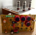
I'm getting a decent amount of noise, and I noticed that my circuit ground has about 25-30mV DC in relation to the chassis. I have the ground connected to chassis through a ground isolator (House GND Kit). The DAC is connected to the ground isolator using that middle pad on the filter board connected to the ground plane.
What's even weirder, is when I bypass the isolator by touching a different chassis wire to the ground, there is a little tiny spark. What could be causing voltage to leak into ground?
What's even weirder, is when I bypass the isolator by touching a different chassis wire to the ground, there is a little tiny spark. What could be causing voltage to leak into ground?
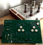
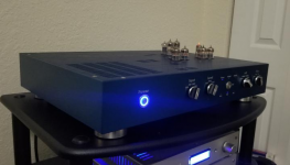
Ignore my post about noise. The connection from the ground of the output board to the ground isolator thing wasn't good. Still don't know why there's a little bit of voltage, but it's fine regardless. I still need to debug the optical and USB, but for now I'm just enjoying it with BNC. Really wanting some nice tubes for it now...
Attachments

For the life of me, I cannot get USB to work. I'm using a WaveIO (http://www.luckit.biz/documents/WaveIO/WaveIO_Infos.pdf).
I have the J6 header of the WaveIO connected as follows to P9 of the ValveDAC:
Data (DT) to pin 5
Word Clock (LR) to pin 11
Bit Clock (BC) to pin 9
Master Clock (MC) to nothing
Vin (V+) to pin 19
And all grounds are connected to the adjacent P9 grounds
P9 pin 1 is connected to an extra contact on my input selection switch. It is wired so that when USB is selected on the switch, P9 pin 1 is then connected to SW3 pin 5 (GND). SW3 pins 1-4 (the other inputs) are connected to nothing.
P9 pin 3 is directly connected to ground using a jumper to P9 pin 4.
The WaveIO J9 has an L8 pin that is described as a mute function, I don't have that connected to anything.
My PC is detecting the WaveIO and the WaveIO driver is detecting the signal rate of the songs just fine.
EDIT: Upon further testing, I think I have a bridged connection somewhere on the ValveDAC. With nothing plugged into P9, pins 17-20 all have continuity to ground.
Last edited:
- Home
- Source & Line
- Digital Line Level
- Valve DAC from Linear Audio volume 13