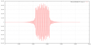
This is the calculated response of my first interpolation filter in the steep mode to your burst, this first filter should be dominant. The burst starts at t = 0 s, the horizontal axis is in seconds and the vertical axis in arbitrary units. I hope this helps.
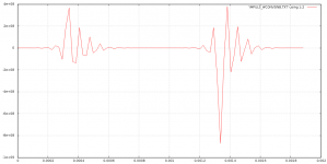
For completeness' sake, the second plot shows the same for the apodizing filter. It shows that at a sample rate as low as 44.1 kHz, 20 kHz is in the apodizing filter's stopband and is hence suppressed.
For completeness' sake, the second plot shows the same for the apodizing filter. It shows that at a sample rate as low as 44.1 kHz, 20 kHz is in the apodizing filter's stopband and is hence suppressed.
Attachments
Last edited:
Marcel, have you checked the filters resulting from your interpolation method in some sort of sim? I have, and it is possible that I have misinterpreted something, but my results are not good. If we use the following start point for the calculations (just like the existing filter in the schematics):
Source load 11,200ohm
Termination Load 800ohm
Fc = 82,000Hz
6th order Linear Phase Low Pass 0.05deg phase error
I get interpolated constants as follows:
C1 = 0.7104
L1 = 3.3881
C2 = 0.4364
L2 = 4.9412
C3 = 0.3060
L3 = 8.6052
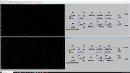
See the attachment for my sims: top is using the INF constants; bottom is using the interpolated constants.
Source load 11,200ohm
Termination Load 800ohm
Fc = 82,000Hz
6th order Linear Phase Low Pass 0.05deg phase error
I get interpolated constants as follows:
C1 = 0.7104
L1 = 3.3881
C2 = 0.4364
L2 = 4.9412
C3 = 0.3060
L3 = 8.6052
See the attachment for my sims: top is using the INF constants; bottom is using the interpolated constants.
Attachments
Something must have gone wrong with the interpolation. It's interpolation between figures 2C and 2D of the pdf file, so the interpolated values must end up somewhere between the values of figures 2C and 2D. By the way, the source impedance is about 5600 ohm single-ended or 11.2 kohm differential.
Marcel, the DC blocking caps are only there to keep high DC out of the transformer primary, correct? If the transformer could handle those voltages, including the 300Vdc single failure voltage we talked about earlier, then do those cap become redundant and are not required in the build?
No, you also need them to ensure that the transformer core isn't driven into saturation during start-up or power-down and to be able to trim the anode voltages for minimum idle channel noise. You can use a much lower working voltage, though: 100 V is enough when the transformer is sufficiently insulated.
You guys are way over my head with the technical discussion but it is fantastic to see the level of interest and vibrant topic for Marcel's wonderful design. I know just how good the 'standard' DSD version sounds so if you can squeeze even more out that will be amazing.
I have a second DSD-version PCB but I think I'll be patient and see how this develops before I do anything with it.
Good luck with you experiments.
I have a second DSD-version PCB but I think I'll be patient and see how this develops before I do anything with it.
Good luck with you experiments.
Last edited:
No, you also need them to ensure that the transformer core isn't driven into saturation during start-up or power-down and to be able to trim the anode voltages for minimum idle channel noise. You can use a much lower working voltage, though: 100 V is enough when the transformer is sufficiently insulated.
Mmmm..I can't seem to get rid of those blocking caps no matter how I try.
OPT saturation at startup/shutdown is not really an issue for me, but trimming the anode voltages is certainly worthwhile, and the caps are needed for that? I assume the caps would also zero the DC offset into the output transformer which at these tiny currents could easily cause problems. On all my diy gear I use little battery powered digital voltage meters to verify DC Offset...just turn it on when I want to check and turn it off once checked, but I don't see anywhere to trim the DC offset in the schematics unless that is what the anode potentiometer actually adjusts. Would probably be worth putting a one of those meters on each channel to be able to keep check and adjust the trim more easily from time to time.
Btw, Marcel, I was interpolating between two wrong sets of numbers (well, one of them was right) in the filter calculator...have fixed that up now and the spreadsheet has been updated and the sims look perfect...very nice to be able to calculate things very easily...thank-you.
From what I've gathered so far is that Marcel's generosity is only matched by his patience. The amount of time he invests in this openly shared project must be substantial.
And on the topic of squeezing out performance, I've been wondering what impact the valve choice for the current switching E88CC valves might have. They're not exactly used as linear devices, but rather as switches. As a consequence it would seem that besides microphonics, noise and longevity, the valve choice in regard to brand and linearity and such would have less of an impact than in a purely analogue circuit? I have some nice S&H E88CC, but I'm not convinced that they'll gain me a significant advantage in this specific circuit. Any thoughts or maybe even experiences with that?
And on the topic of squeezing out performance, I've been wondering what impact the valve choice for the current switching E88CC valves might have. They're not exactly used as linear devices, but rather as switches. As a consequence it would seem that besides microphonics, noise and longevity, the valve choice in regard to brand and linearity and such would have less of an impact than in a purely analogue circuit? I have some nice S&H E88CC, but I'm not convinced that they'll gain me a significant advantage in this specific circuit. Any thoughts or maybe even experiences with that?
Mmmm..I can't seem to get rid of those blocking caps no matter how I try.
Maybe you could get rid of half of them with a well-insulated transformer, if you don't mind the schematic looking asymmetrical.
OPT saturation at startup/shutdown is not really an issue for me, but trimming the anode voltages is certainly worthwhile, and the caps are needed for that?
Using RV1 and RV2, you can trim the difference between the DC voltages at the anodes until you get minimum idle channel noise. This wouldn't work with a transformer and without DC blocking capacitors, because the primary winding would just DC short the anodes.
One single DC blocking capacitor per channel would be sufficient to solve this, though, if the common-mode termination of the filter can be rearranged somehow, or the filter is made differential. Using a single 10 uF capacitor would then give the same frequency below which the load impedance and noise modulation starts increasing as you otherwise would get with two 20 uF capacitors.
I assume the caps would also zero the DC offset into the output transformer which at these tiny currents could easily cause problems.
Yes, but a single capacitor per channel could also do that.
Well that is interesting Marcel: asymmetrical schematic is fine; half the DC blocker caps is very fine; double the noise modulation suppression bang-per-uF is super-fine. One 15uF per channel gets circa 14Hz corner cutoff on the noise modulation thingamy. There has got to be tradeoffs though...
I can calc out differential filters for each channel but would require twice the number of inductors and caps to get the job done. No idea how to alter the filter termination to avoid this though...
I can calc out differential filters for each channel but would require twice the number of inductors and caps to get the job done. No idea how to alter the filter termination to avoid this though...
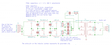
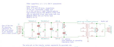
I was thinking about one of the attached circuits connected to a main board where one of the DC blocking capacitors is replaced with a short and the other has only 100 V DC working voltage (all assuming a well-insulated signal transformer).
In one case, the 180 ohm common-mode termination resistor gets a capacitor in series that is much smaller than the DC blocking capacitor, yet large enough to have a reactance much smaller than 180 ohm at 82 kHz. Common-mode hash is then filtered off as effectively as in the original circuit, the termination still prevents nasty resonances in the common-mode response.
In the second case, there is no common-mode filtering at all except for the two 8.2 nF capacitors to ground on the main board. You then rely more on the transformer to get rid of it. Note that C2 and C6 are not connected to ground anymore.
Attachments
By the way, I'm not going to try it out, but I wonder what would happen to a Jensen JT-11SSP-7MPC with -300 V +/- tolerance on the primary. The insulation voltage spec is 250 V RMS (so 353.5 V peak) 60 Hz for one minute from the primary or secondary to the shield and case. Using such voltages for a longer time is explicitly not recommended, but if they would only result in a short to a grounded electrostatic shield rather than to the secondary, it would still be safe to touch the outputs.
Thanks so much for the filter options Marcel. Looks like I should keep a twin primary winding just in case the filter needs terminating that way.
Next question. In the LA article you mention up to 10mVrms of out-of-band noise in PWM8 mode. It looks like this is the noise level at the output of the dac after the 6th order filter and output transformer. Have the frequencies of this remaining noise been measured or do you know the spectrum of frequencies and levels to target with the filter. I'm trying to establish a baseline for acceptible minimum performance of the filter based on the noise spectrum either remaining after the filter or to be targeted by the filter in general.
Obviously the original dac uses a sixth order filter and there are good reasons for that but the DSD only version ended up with 3rd order filter.
- Home
- Source & Line
- Digital Line Level
- Valve DAC from Linear Audio volume 13