I just don't get it. I am not trying to be critical as I know this seems very popular by the number of designs and products, but why would one go through the trouble of a DAC with .000-something distortion to add a tube buffer and generate massive distortion?
You've posted in the wrong thread, that isn't how this DAC works.
So how are you guys getting on with your builds - anyone close to listening yet?
For my part, I've been listening to some native DSD material on both my Valve DAC and my DSC2 - sounds fantastic.
I purchased some more DSD256 albums from NativeDSD - if you're interested in trying some such material you might want to be aware that they're offering a 20% reduction on just about their whole catalogue for 'Black Friday'.
Homepage - NativeDSD Music
The AK4137 (when it becomes available again at a reasonable cost), specifically in the shape of Pavel's (DIY Audio member ppy) board, looks to be a good option for the DSD-only version of Marcel's DAC. It should plug onto the DAC board using either the Amanero-style header or the ufl connections.
I haven't looked into the AK4137 option, but anything that can drive and meet the timing requirements of a DSC2 v2.5.2 DAC can also drive and meet the timing requirements of a raw DSD valve DAC running on the bit clock, so assuming Pavel has designed his board to be DSC2 compatible, it's also raw DSD valve DAC compatible.
Last edited:
For the raw DSD version, the test points called Phole1...Phole10 are just mounting holes. Phole1...Phole8 are meant for mounting the main board and Phole9 and Phole10 are for mounting the board that connects to the Amanero-style connector, if any.
The test points P1, P2, P5 and P6 in the DAC cores are leftovers from the original valve DAC that don't serve any purpose. I originally thought they might come in handy during trimming of the delay between clock/clockn and clock5/clockn5, but in fact they were not needed at all.
The test points P1, P2, P5 and P6 in the DAC cores are leftovers from the original valve DAC that don't serve any purpose. I originally thought they might come in handy during trimming of the delay between clock/clockn and clock5/clockn5, but in fact they were not needed at all.
-300V HT
How critical is the voltage on the HT supply?
I have a 260VAC transformer instead of the specified 230V trafo.
I will drop voltage by using higher R values in the RC nodes of the supply line.
May I drop a little less or more voltage than the 41 volts that calculation suggests? Would like to use resistors from the box.
Hi,
changed plans for me. I will not build my DAC. Added my circuit board + suitable R-core transformer in the Swap Meet forum if anyone is interested.
Thanks Ray and Marcel!
And for the others in the group purchase, good luck with your builds, will be interesting to see the results!
/ Micke
changed plans for me. I will not build my DAC. Added my circuit board + suitable R-core transformer in the Swap Meet forum if anyone is interested.
Thanks Ray and Marcel!
And for the others in the group purchase, good luck with your builds, will be interesting to see the results!
/ Micke
How critical is the voltage on the HT supply?
I have a 260VAC transformer instead of the specified 230V trafo.
I will drop voltage by using higher R values in the RC nodes of the supply line.
May I drop a little less or more voltage than the 41 volts that calculation suggests? Would like to use resistors from the box.
My main worry would be start up at 10 % too high mains voltage. I've dimensioned many things for a maximum voltage at start-up of -400 V. -400 V at 10 % above nominal mains is -363 V at nominal mains.
During start-up, only the voltage divider R47, R43, R139, D16, R140, R141 loads the -300 V supply, so the voltage drop across R132 and R136 will be less than normal and the transformer will deliver a bit more voltage than normal. If needed you could consider replacing R136 with a series connection of a Zener and a resistor, to reduce the difference in voltage drop between start up and full operation.
Once everything is heated up, if you manage to get the negative supply somewhere between -290 V and -330 V at nominal mains voltage, that should be OK.
Do you happen to know the unloaded voltage of your transformer (or equivalently the regulation) and the VA rating?
Do you happen to know the unloaded voltage of your transformer (or equivalently the regulation) and the VA rating?
Thank you, as far as I remember, it's 290V unloaded, and 40VA. Can't check at the moment because I have to pull it from another build.
I did a sim in PSU Designer, assuming 10% regulation. This does look ok, given that C1-47uF is a 500V cap.
I will see how it turns out, the Zener is a good idea and another option.
Attachments
Hello again. Just was thinking of a variant of the RAW DSD512..
I'm been thinking of a version of this with 6SN7s. With two triodes per envelope and medium mu, it got me thinking as the 10mA differential output should be used to drive a push pull configuration of two 6AS7s in OTL for headphones (I'm designing a PP 6SN7/6AS7 OTL headphone amp at the moment in LTSpice). Three 6SN7s could provide the 6 triodes needed in small neat headphone sized amp package.
* 6SN7 coping with MHz in real life vs simulation. Gut feeling is that it probably won't have a problem.
* Cross talk vs higher B+ to Va/Ia - I suspect this may cause more RF issues in close proximity. one option is to allow low Hz (DC) and high Hz (rise/fall of the digital signal) only using a blocking filter.
* Reconstruction filter - the temptation to put this between the 6AS7 and headphones but would have to play with a simulation.
I may quickly knock up a simple DSD512 clocked LTSpice simulation - perhaps use a input file with DSD512 and then output a WAV file and see (although this may take some time to simulate).
Looking in a different direction, I have wondered previously about a version of Valve DAC using a Russian subminiature valve equivalent to the E88CC to make the board smaller/cheaper - 6S28B or 6S29B seem to be suitable but are only single triodes so the opportunity for a smaller board largely evaporates with the need for twice as many valves.
IIRC 6N16B is a well regarded dual triode sub-min equivalent to the 6SN7?
IIRC 6N16B is a well regarded dual triode sub-min equivalent to the 6SN7?
6N16B double triode miniature tube → OTHER tubes → Tubes-Store.com
Hmm interesting.. less power handling but that's to be expected. I think it depends a little on what it's driving on the next stage - 6AS7 needs a fair whack of current.
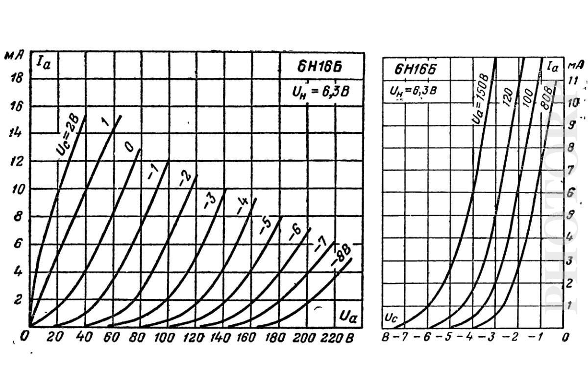
I can't read Russian but ... hang on full stats here: 6N16B-VI Double Triode Miniature Tube MELZ Soviet Russian NEW all photos and images | photorp.com
curves: https://photorp.com/media/photorp/vintage-tubes/6n16b-vi-double-triode-miniature-tube-1.jpg
Hmm interesting.. less power handling but that's to be expected. I think it depends a little on what it's driving on the next stage - 6AS7 needs a fair whack of current.
I can't read Russian but ... hang on full stats here: 6N16B-VI Double Triode Miniature Tube MELZ Soviet Russian NEW all photos and images | photorp.com
curves: https://photorp.com/media/photorp/vintage-tubes/6n16b-vi-double-triode-miniature-tube-1.jpg
Last edited:
Do - edit timed out as I was playing with the load line calculator (Triode / Pentode Loadline Simulator v.1.0 (20161216 [url]www.trioda.com)[/url]). Looking at the load line, in the architecture we have for the valveDAC the valve will see the 16Kohm resistance (Ra) as it's got two 32R in parallel. A 0-5V grid (not using ±2.5), 153Ua, 16K Ra, will see ~ 2.59mA Iq (10mA at 0Vg, 3mA at about -5Vg) mu of 22.5V/V. There's still a little more you could give the tube by increasing the anode voltage.
Maybe I'm wrong and need of another coffee after a 5am start..
Maybe I'm wrong and need of another coffee after a 5am start..
Last edited:
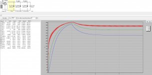
Well got the 6SN7 model running on LTSpice lol - DSD512 simulation 

This is literally the same voltages so probably not the best for the 6SN7's performance but it's 'working' (there needs to be a load of testing for distortion etc) plus I've not put in part of the filter (Lundhl transformer not in) so there's likely to be a load of digital signals output. I also had to use the 74HC74 which is 0.5V instead of the 74HCT74 which is 1.3V due to LtSpice model availability.
This is literally the same voltages so probably not the best for the 6SN7's performance but it's 'working' (there needs to be a load of testing for distortion etc) plus I've not put in part of the filter (Lundhl transformer not in) so there's likely to be a load of digital signals output. I also had to use the 74HC74 which is 0.5V instead of the 74HCT74 which is 1.3V due to LtSpice model availability.
Last edited:
- Home
- Source & Line
- Digital Line Level
- Valve DAC from Linear Audio volume 13