What exactly drifted during those three days and by how much? Just the last ppm of the frequency, which would be irrelevant for an audio DAC, or the close-in or far-off phase noise?
Don't know. Don't have the gear to measure it. I am reporting perceived sound quality changes and observed industry practices only. I do not claim 'proof.'
Also, completely agree with your stated concerns, which is what I was trying to allude to. I still think the 'always on' approach is worth its added engineering effort.
Last edited:
A quick and dirty approach is to use one clock. In my case 99% of my library is at one sample rate. I use a clock optimized to that rate and give it its own chassis and power supply and leave it on 7/24. Chassis is optimized to clock duty(vibration/EMI) The software uses SOX to convert material on the fly to that sample rate. 99% is untouched. If I understand correctly, nautiboy's approach also uses software to convert on the fly to one sample rate. Problem solved?
It has the additional benefit of saving the cost of one of these expensive clocks.
It has the additional benefit of saving the cost of one of these expensive clocks.
If I understand correctly, nautiboy's approach also uses software to convert on the fly to one sample rate.
No. HQ Player upsamples preserving the relationship to the original sample rate (i.e. multiples of 44.1KHz or 48KHz as appropriate). My solution has two oscillators. This is important as 48KHz family data is becoming more prevelant.
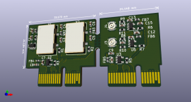
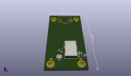
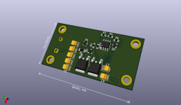
Schematics and renders of the external oscillators inputs board and stand-alone, always-on Crystek clock module (2 layers board). Connect 1 or 2 single-ended clocks to J3 and J4 of the inputs board. Using external clocks has been my original plan, and I reused the schematic a couple pages back, and removed the sine-to-square wave converters.
Attachments
Last edited:
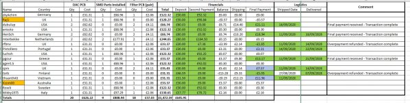
Latest GB sitrep attached. I'm still waiting on some final payments for shipped PCBs.
My friend's house move is almost complete and he'll soon be in a position to progress the smd soldering. Apologies for the delay.
Has anybody made progress with the boards that have been delivered?
Ray
My friend's house move is almost complete and he'll soon be in a position to progress the smd soldering. Apologies for the delay.
Has anybody made progress with the boards that have been delivered?
Ray
Attachments
Last edited:
Very dumb open question but why not clock the tubes at a high rate (ie 3MHz) then run the digital switching data stream at 192Khz then upscale using software?
Surely this shifts the aliasing and switching/clock harmonics into an easy filterable region?
My limited understanding of valves is that they can happily 'switch' at this speed although circuit design is made more complex due to the increasing RF antenna properties of the tracks. Or is it the voltage required to drive the swings of signal at that rate?
Last edited:
Very dumb open question but why not clock the tubes at a high rate (ie 3MHz) then run the digital switching data stream at 192Khz then upscale using software?
Surely this shifts the aliasing and switching/clock harmonics into an easy filterable region?
My limited understanding of valves is that they can happily 'switch' at this speed although circuit design is made more complex due to the increasing RF antenna properties of the tracks. Or is it the voltage required to drive the swings of signal at that rate?
I think I've answered my own question here.
Miles wrote this: Tube rise time and slew rate
And following grid drivers: Design Considerations
Rule of thumb 1:10 with 3MHz -> 333ns/Vsignal swing is better serviced by a 33ns swing. So you'd need to drive the gate to ensure an accurate signal.
In short - doable but exponentially additional cost (adding a power amp grid driver to drive each of the DAC signal tubes).
Still... you know you want to

Still... you know you want to
Last post on this - it looks as if Marcel does this on the crystal oscillator at 27MHz already (using a gate driver).
Schematics and renders of the external oscillators inputs board and stand-alone, always-on Crystek clock module (2 layers board). Connect 1 or 2 single-ended clocks to J3 and J4 of the inputs board. Using external clocks has been my original plan, and I reused the schematic a couple pages back, and removed the sine-to-square wave converters.
I took a look at your project and, having (partly) understood what you're trying to do, you now have my attention
I'm considering andrea_mori work for the the external clock part: can you confirm you're expecting a cmos square wave as external clock?
Thanks,
Mirko
Hi Nick,
In the original valve DAC, the bottom differential pair in each DAC core is switching at 27 MHz. The 27 MHz comes from a valve crystal oscillator (ECC81) via two valve buffers (2 times EF80). The digital input signal is converted into a 27 Mbit/s noise-shaped single-bit digital signal that drives the upper differential pairs. This conversion is done by an SRC4392 asynchronous sample rate converter chip and an FPGA board, the grids of the upper differential pairs are driven by a 74AHCT74.
In the raw-DSD version, the bottom differential pair is driven by some solid-state circuitry with either 22.5792 MHz or 24.576 MHz, or a frequency that is 2, 4 or 8 times lower. The upper differential pairs are driven by a 22.5792 Mbit/s or 24.576 Mbit/s or 2, 4 or 8 times lower noise-shaped single-bit digital signal. That signal comes from outside the DAC, Ray generates it with a computer. Level shifting and upper differential pair grid driving is done in the same way as in the original valve DAC.
Filtering aliases and clock harmonics is easy as they are at quite high frequencies, but there is also out-of-band quantization noise due to the conversion to a noise-shaped single-bit signal. That's why the filter cut-off frequency should not be made too high.
As I don't understand your question, I'm not sure if this answers it, but I hope it does anyway.
Regards,
Marcel
Last edited:
I took a look at your project and, having (partly) understood what you're trying to do, you now have my attention
I'm considering andrea_mori work for the the external clock part: can you confirm you're expecting a cmos square wave as external clock?
Thanks,
Mirko
yes. Valve Dac needs a TTL/CMOS signal clock. I also am considering a pair of Andrea's well tempered clocks. According to him, these clocks generate sine wave outputs. Sine-to-square wave converters are required.
Last edited:
Hi Nick,
In the original valve DAC, the bottom differential pair in each DAC core is switching at 27 MHz. The 27 MHz comes from a valve crystal oscillator (ECC81) via two valve buffers (2 times EF80). The digital input signal is converted into a 27 Mbit/s noise-shaped single-bit digital signal that drives the upper differential pairs. This conversion is done by an SRC4392 asynchronous sample rate converter chip and an FPGA board, the grids of the upper differential pairs are driven by a 74AHCT74.
In the raw-DSD version, the bottom differential pair is driven by some solid-state circuitry with either 22.5792 MHz or 24.576 MHz, or a frequency that is 2, 4 or 8 times lower. The upper differential pairs are driven by a 22.5792 Mbit/s or 24.576 Mbit/s or 2, 4 or 8 times lower noise-shaped single-bit digital signal. That signal comes from outside the DAC, Ray generates it with a computer. Level shifting and upper differential pair grid driving is done in the same way as in the original valve DAC.
Filtering aliases and clock harmonics is easy as they are at quite high frequencies, but there is also out-of-band quantization noise due to the conversion to a noise-shaped single-bit signal. That's why the filter cut-off frequency should not be made too high.
As I don't understand your question, I'm not sure if this answers it, but I hope it does anyway.
Regards,
Marcel
Yup - it also gives direction for my curiosity
How the signal is digitally converted into a noise-shaped single-bit signal in the original valve DAC is described in more detail in sections 2, 3, 7, 8 and 9 of https://linearaudio.net/sites/linearaudio.net/files/03 Didden LA V13 mvdg.pdf
How it is done in the software Ray uses is a trade secret, but from what I've read about it, I get the impression that it is done in a rather similar way although the details will be different. For example, Ray doesn't need any asynchronous sample rate converter because everything is synchronized to the clock that drives his DAC.
How it is done in the software Ray uses is a trade secret, but from what I've read about it, I get the impression that it is done in a rather similar way although the details will be different. For example, Ray doesn't need any asynchronous sample rate converter because everything is synchronized to the clock that drives his DAC.
How the signal is digitally converted into a noise-shaped single-bit signal in the original valve DAC is described in more detail in sections 2, 3, 7, 8 and 9 of https://linearaudio.net/sites/linearaudio.net/files/03 Didden LA V13 mvdg.pdf
How it is done in the software Ray uses is a trade secret, but from what I've read about it, I get the impression that it is done in a rather similar way although the details will be different. For example, Ray doesn't need any asynchronous sample rate converter because everything is synchronized to the clock that drives his DAC.
I'd hazard a guess that the valves are acting as DSD amplification in a push-pull configuration and the low pass filter is then being used to reconstruct the output analogue (akin to a D class amp without the need for gallium arsenide for switching speed).
So getting from other formats to DSD etc is the pain. OSX's internal codecs support conversion to PCM (probably because the hardware choice is easier for mobile). It's easy to make a OSX device that takes PCM, however you'd need a FPGA to take the PCM and output the DSD if that's the option. OSX hi-res players seem to top out at DSD256 for some reason but there are plenty that support all the varying outputs - they all come out as PCM in the end to the hardware unless you bypass the codec/hardware and take DSD direct.
The use of a beagle board simply allows him to bypass and just take DSD direct as an output.
I would be wondering if there's a way with serial registers to simply take PCM and create the DSD stream, clocked out.
Anyway I digress
Some ASRC chips have built-in sigma-delta modulators, for example the AK4137, so you could also use those instead of an FPGA module to convert PCM to a sigma-delta modulate (DSD is a Sony/Philips trade name for a sigma-delta modulate). An FPGA module gives more control and more possibilities to tweak things. You need much more than just a shift register to convert PCM to a usable sigma-delta modulate.
So getting from other formats to DSD etc is the pain. OSX's internal codecs support conversion to PCM (probably because the hardware choice is easier for mobile). It's easy to make a OSX device that takes PCM, however you'd need a FPGA to take the PCM and output the DSD if that's the option. OSX hi-res players seem to top out at DSD256 for some reason but there are plenty that support all the varying outputs - they all come out as PCM in the end to the hardware unless you bypass the codec/hardware and take DSD direct.
or you could just run HQ Player and not worry about it;
Signalyst
In my project, all the 'heavy lifting' is performed on a Linux computer running HQ Player (which is where the 'trade secrets' Marcel mentioned reside - they're not my trade secrets).
The use of a beagle board simply allows him to bypass and just take DSD direct as an output.
The HQ Player workstation streams the DSD over a network connection to the beaglebone, which is an end-point appliance that 'simply' renders the data to the DAC.
- Home
- Source & Line
- Digital Line Level
- Valve DAC from Linear Audio volume 13