The board is clock agnostic. It just needs two clock inputs via u.fl connectors. People can use any clocks that they want. I can do a separate clock board for NKD/Crystek. Any interest or preference?
Putting the entire clock input section into a separate pluggable module is interesting and I have been thinking about it as well. So, LVPECL, LVDS or CML clock format, instead of just TTL, can also be used.
Putting the entire clock input section into a separate pluggable module is interesting and I have been thinking about it as well. So, LVPECL, LVDS or CML clock format, instead of just TTL, can also be used.
Last edited:
Yes, I understand that the board is agnostic wrt clocks, I was just thinking that the option of pluggable oscillators would give more options and potentially make things simpler as a starting point but I respect that it's your decision on how you take it forward.
Last edited:

Reply to post 879 of this thread: If I interpret the third plot from post #2604 of the thread you linked to correctly, there is a peak of -52.75 dBc at 3/2 times the desired clock frequency. I'm pretty sure that would be a disaster when the DSD512 signal comes from a straightforward single-bit sigma-delta modulator. I'd rather use oscillators at 22.5792 MHz and 24.576 MHz and get rid of the doubler.
Last edited:
Yes, I understand that the board is agnostic wrt clocks, I was just thinking that the option of pluggable oscillators would give more options and potentially make things simpler as a starting point but I respect that it's your decision on how you take it forward.
yes. I agreed. I will draft something, allowing clock options. Crystek has a new clock. Use this one?
https://www.crystek.com/crystal/spec-sheets/clock/CCHD-957.pdf
Did a bit of research and I think moving all the clock parts to a separate board is doable. How about plugging the oscillators onto the main board vertically, similar to how a GPU plugs into a PCIe slot? Illustrated on the first row, second column of the pdf. I have been looking for 100 ohm differential card edge connectors, and there are not many.
See
https://www.carlisleit.com/wp-content/pdfs/prodinfo/CardEdgeConnectors.pdf
See
https://www.carlisleit.com/wp-content/pdfs/prodinfo/CardEdgeConnectors.pdf
Last edited:
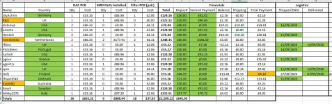
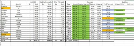
I finally received an invoice from Fedex for the Import duty and tax for the main PCBs but fortunately it was a little less than my estimate so there is a small decrease in the cost of each board. At least now we have the final figures for the board costs and can start sorting out final payments - at least for everyone who's boards have already been sent.
I've attached an updated spreadsheet screengrab reflecting these costs. Looking at the 'Final Payment' column, if the cell for you is blue can you please send me a payment for the amount shown - this will close the transaction. If your cell is orange you are due a refund for an overpayment and I'll process these later this evening. If your cell has no colour no further payment/refund is due at this time.
When you make payments to me please use PayPal family and friends to avoid my incurring fees.
I'm still missing two delivery addresses for the subscriber names shown in orange.
I'm hoping to get the soldering underway next week.
Has anyone started to assemble their project yet?
Cheers
Ray
Attachments
Last edited:
I have been looking for 100 ohm differential card edge connectors, and there are not many.
See
https://www.carlisleit.com/wp-content/pdfs/prodinfo/CardEdgeConnectors.pdf
If the connector is electrically short (that is, if the signal can bounce back and forth in the connector a few times within the signal's rise or fall time), the characteristic impedance will not be very critical. What is the shortest rise or fall time of the clock signals? (I should know, but I have no access to the datasheets of your LVDS drivers at the moment.)
Ciao,
I’m wondering if I’m underestimating the effect of having the BBB inside the same chassis as the dac. I’m interested in your thoughts and projects because I was thinking about just doing a box-in-a-box for the bbb and then isolate/reclock. Do you think there should be audible benefits in a two-chassis implementation? Is it worth the extra care one must give to the clock/signal across more than a couple of centimeters?
I’m an IT guy, not an electronic engineer so be gentle, I’m just asking ��
Cheers,
Mirko
I am using the TI series of LVDS drivers, because it has SOIC-8 and SOT-23 footprints with different pinouts. I am using both footprints to avoid using vias to route traces to the back side of the board.
Datasheet
https://www.ti.com/lit/ds/symlink/sn65lvds1.pdf
And the answer to the question of what is the rise or fall time is, according to Table 7.7, a maximum of 0.7ns.
I think the Carlisleit connector is okay to use. It is not a special order item, unlike those from Samtec and Molex, and is in stock for sale at Digi-Key for around $5.
I read that when two oscillators are placing close together, they may affect each other. So, it is a good idea to have some separation between the two. I am also wondering, instead of building a mezzaine, looking architecture and high-tech, the entire clock system may actually perform better by having two separate clock pcbs, each having an oscillator on top, and a power supply regulator underneath. They can connect to the DAC side of the board through existing u.fl connectors.
Last edited:
And the answer to the question of what is the rise or fall time is, according to Table 7.7, a maximum of 0.7ns.
correction: It should be typical 0.7ns and a maximum of 1ns.
And the answer to the question of what is the rise or fall time is, according to Table 7.7, a maximum of 0.7ns.
Assuming a speed of propagation of 200 000 000 m/s, the signal can travel 14 cm in 0.7 ns, so it can go back and forth four times over a distance of 1.75 cm.
I think the Carlisleit connector is okay to use. It is not a special order item, unlike those from Samtec and Molex, and is in stock for sale at Digi-Key for around $5.
I agree with you if the contacts are shorter than 1.75 cm or if it has the correct impedance or both.
I read that when two oscillators are placing close together, they may affect each other. So, it is a good idea to have some separation between the two. I am also wondering, instead of building a mezzaine, looking architecture and high-tech, the entire clock system may actually perform better by having two separate clock pcbs, each having an oscillator on top, and a power supply regulator underneath. They can connect to the DAC side of the board through existing u.fl connectors.
I have seen serious problems due to unintended coupling between oscillators at work, but always with LC oscillators working at very close frequencies that were placed within a few millimetres from each other. I would not expect any trouble with crystal oscillators with a frequency difference of a few percent, like you use.
Last edited:
Ciao,
I’m wondering if I’m underestimating the effect of having the BBB inside the same chassis as the dac. I’m interested in your thoughts and projects because I was thinking about just doing a box-in-a-box for the bbb and then isolate/reclock. Do you think there should be audible benefits in a two-chassis implementation? Is it worth the extra care one must give to the clock/signal across more than a couple of centimeters?
I’m an IT guy, not an electronic engineer so be gentle, I’m just asking ��
Cheers,
Mirko
I find it difficult to say anything useful about that, but maybe Ray can, as he has experience with putting a BBB close to a DAC.
I’m wondering if I’m underestimating the effect of having the BBB inside the same chassis as the dac.
My Valve DAC, which sounds fantastic (and I think is why people are interested in building their own versions) has the BBB and reclocker in the same chassis as the DAC board so I wouldn't be overly concerned about it. Could it be improved by separating the BBB? - maybe, but it is unlikely to be more than a small difference, if it's discernable. Perhaps I'll find out with a second build, when it'll be handy to have the original build available as a baseline.
In the picture, the BBB/reclocker are under the main board in the vicinity of the yellow caps/large brown resistors.

Last edited:
Thanks Marcel, Ray, agent for your kind replies.
@Ray: your realizations are amazing and incredibly your dac interior looks even better. I wish I'll reach a similar result. I came across the Valve DAC after reading a lot on the DSC2 and Pavel's work. Originally I was more keen on the DSC2 and then found this tube implementation... love at first sight")
If I may ask: how you other diyers put the pieces together? I would try PPY reclocker but could not find an open GB so I found others went with Ian's fifo/clock and others with Cronus/Hermes. Any advice on this?
Best,
Mirko
@Ray: your realizations are amazing and incredibly your dac interior looks even better. I wish I'll reach a similar result. I came across the Valve DAC after reading a lot on the DSC2 and Pavel's work. Originally I was more keen on the DSC2 and then found this tube implementation... love at first sight
If I may ask: how you other diyers put the pieces together? I would try PPY reclocker but could not find an open GB so I found others went with Ian's fifo/clock and others with Cronus/Hermes. Any advice on this?
Best,
Mirko
PPY posted gerber.
https://puredsd.ru/BBBreclk.zip
You can upload this to
PCB Prototype & PCB Fabrication Manufacturer - JLCPCB
and have it made inexpensively.
https://puredsd.ru/BBBreclk.zip
You can upload this to
PCB Prototype & PCB Fabrication Manufacturer - JLCPCB
and have it made inexpensively.
In the picture, the BBB/reclocker are under the main board in the vicinity of the yellow caps/large brown resistors.
So that's basically the same digital at the bottom, analogue and mixed-signal at the top strategy that I used for the FPGA board and other digital circuitry of the original valve DAC. It also worked well for me
PPY posted gerber.
https://puredsd.ru/BBBreclk.zip
You can upload this to
PCB Prototype & PCB Fabrication Manufacturer - JLCPCB
and have it made inexpensively.
I didn’t know it was so easy nowadays, thanks!
- Home
- Source & Line
- Digital Line Level
- Valve DAC from Linear Audio volume 13