More annoying than demoralising. This dac will get done, but it needs to happen while I am able to give a bit of time to it, which unfortunately ebbs and flows with my work. Should have the Chip Quick stuff tomorrow and with any luck I will whip off J5 tomorrow night and see if that makes things better.
Then I am away for the rest of the week but hopefully I will have some sort of an answer before leaving. Replacement Hirose connectors are about a week away, should they be required.
Then I am away for the rest of the week but hopefully I will have some sort of an answer before leaving. Replacement Hirose connectors are about a week away, should they be required.
Keep in good spirits! It's a complex build. I've had to totally redesign and reorder my input boards (which I have 4 extra of if anyone wants one), and my 6.3VDC supply has been a nightmare, I'll finally have that sorted out this week. Turns out 3 amps is a lot of current/heat lol.
That Chip Quick stuff is excellent. Removed J5 without issue and without fuss. So easy.
Measured the problem traces with J5 removed and it seems as though all is good and that the problem was a solder bridge under the Hirose connector. Impossible to see even with the magnifying glass of course, but at least it seems like the pcbs are ok and that U9 and other chips are not the problem. Shall solder on another J5 and see if I can do a better job this time...
Measured the problem traces with J5 removed and it seems as though all is good and that the problem was a solder bridge under the Hirose connector. Impossible to see even with the magnifying glass of course, but at least it seems like the pcbs are ok and that U9 and other chips are not the problem. Shall solder on another J5 and see if I can do a better job this time...
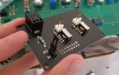
Good news...the relays are clicking when I twist the selector switches. Most of the time at least, but not always. Definite progress though. No sound, but still only have the JLSounds USB board that may or may not be wired up correctly so will have to set up a SPDIF input.
Not sure if the relays stay open or whether they close again, but they do click.
Not sure if the relays stay open or whether they close again, but they do click.
Keep in good spirits! It's a complex build. I've had to totally redesign and reorder my input boards (which I have 4 extra of if anyone wants one), and my 6.3VDC supply has been a nightmare, I'll finally have that sorted out this week. Turns out 3 amps is a lot of current/heat lol.
Sonny, can you please remind me what inputs you have on your input board?
It can do 5v or 3.3v optical, then two general SPDIF inputs with isolation transformers. BNC/coax or AES is determined by the resistor on the VavlveDAC board, so the input board is agnostic. It doesn't use the RX1 set of inputs.
If you want one, I have 4 more. You can have it for free + shipping.
If you want one, I have 4 more. You can have it for free + shipping.
Sonny, can you please remind me what inputs you have on your input board?
Attachments
That means the sigma-delta is running in mode 0, its default mode that only produces silence.
Do you see 3.3 V across all sigma-delta mode switch contacts but one? Any illegal code (more or less than one line pulled to ground) coming out of the sigma-delta mode selection switch results in mode 0.
(I don't know by heart what other conditions lead to mode 0 and I can't look it up right now - to be continued.)
In the modes that can produce sound, the signal will look more irregular.
Last edited:
I just looked in my Verilog code and there are three ways to get the sigma-delta modulators into mode 0:
-Illegal code from the mode selection switch SW1
-Making sel4192 = 0 (P9 pin 1 low) and mutei2sin = 1 (P9 pin 3 high)
-Making sel4192 = 0 (P9 pin 1 low) and providing no bit clock at bcki2sin (P9 pin 9), or one with a much too low frequency (< 100 kHz)
So it can simply be in mode 0 because you selected the I2S input without providing an I2S signal, or muted the I2S input. Disconnecting P9 pin 1 should then change the mode and make the signal between R96 and ground more irregular.

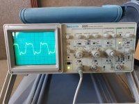
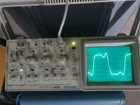
Disconnected P9 entirely and I'm not sure if this is what you mean by irregular (see images - Chaos first, PWM4 and then PWM8). Looks like PWM8 is not quite right, assuming the others look suitably irregular. Will now measure the voltages in the various switch positions on SW1, then go look for some bits to make up a SPDIF input.
Attachments
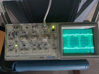
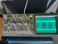
Assuming R64 has the correct value, the only reason I can think of why chaos and PWM4 work but PWM8 not is a lose contact somewhere in the path from SW1 contact 3 via R64 to J4 pin 62. Anyway, you will see that when you check whether there is 3.3 V across open SW1 contacts. If there is nothing else wrong, you should still get sound in the chaotic and PWM4 modes.
Have rigged up two SPDIF inputs (one from JLSounds card and one from Pioneer UDP LX-5000) but still no sound.
The switches are not properly functional. Testing when everything is turned off I get correct resistances between the switch contacts and the relevant pin inside J4 (330R). Apply power though and some of the voltages are just not correct and on top of this the behaviour/voltages are different after I measured several of the switches and then come back to the first ones, like the logic is not working consistently.
For instance, upon first turning on, the input selector SW3 in position 1 reads correctly in all four switch positions, as does the second position, but the third position and fourth position are all incorrect. See below...
Measuring SW3.1...
Switch Pos 1 0v
Switch Pos 2 3.3V
Switch Pos 3 3.3V
Switch Pos 4 3.3V
Measuring SW3.2...
Switch Pos 1 3.3v
Switch Pos 2 0V
Switch Pos 3 3.3V
Switch Pos 4 3.3V
Measuring SW3.3...
Switch Pos 1 0v
Switch Pos 2 0V
Switch Pos 3 0V
Switch Pos 4 0V
Measuring SW3.4...
Switch Pos 1 0v
Switch Pos 2 0V
Switch Pos 3 0V
Switch Pos 4 0V
So, at any one time I seem to have 2-3 inputs selected. SW2 and SW1 are populated (apart from Surprise elements) and have similar problems. SW4 is hard-wired SW4.3-SW4.4 to 'loud' yet all four pins are connected to ground when the power is on, but not when it is off when only SW4.3 and SW4.4 are connected to ground.
J4 seems easier to debug than J5 and I am unable to find any pins tied together that are not ground and as mentioned earlier all SW1/2/3/4/5 to J4 resistances are correct, as are P9-J4 and P7-U8. I have no clue what is going on here. Perhaps I have somehow damaged U8? Maybe there is a J5-U8 connection that is not great?
- Home
- Source & Line
- Digital Line Level
- Valve DAC from Linear Audio volume 13