I use a 4th order to avoid clicks and pops changing from DSD to PCM or v.v. Daphile upsamples all to DSD256
I don't understand how a fourth order low pass filter can eliminate the pops and clicks from format changeover, which are transient events within the audio band - hence the need for an appropriate muting arrangement.
The folks on the noDAC thread (not the DSC1 thread) typically don't use a FIRDAC at all, but still rarely go above third order. My valve DAC has a two-tap FIRDAC with half a clock cycle delay, so the first notch is at 2.8224 MHz when playing DSD64.
I anticipate trying a number of different filter arrangements to find what works best for me. I'll probably start with your suggested 3rd order Butterworth filter and take it from there.
Ray
I don't understand how a fourth order low pass filter can eliminate the pops and clicks from format changeover, which are transient events within the audio band - hence the need for an appropriate muting arrangement.
I only have clicks when start 1st time and when close the listening sessions with Daphile.
All relays & FF only degrade the sound.
Last edited:
I only have clicks when start 1st time and when close the listening sessions with Daphile.
What I'm saying is that I don't think you absence of pops/clicks can be attributed to your LP filter.
What I'm saying is that I don't think you absence of pops/clicks can be attributed to your LP filter.
Are you saying the cut off frequency can't be related to the suppression?
The purpose of the filter is to stop ultrasonic quantization noise before it does any harm (cause audible intermodulation, fry your tweeters, disturb your cat, disorient any nearby bats, whatever) and to pass the part of the signal spectrum that is audible for humans. The pops and clicks are normally in the audible part of the spectrum, so if the filter has an impact on them, that is very unexpected.
Are you saying the cut off frequency can't be related to the suppression?
You can hear the pops and clicks so they must be in the audible band.
The LP filter is designed to allow through everything in the audible band and suppress noise above the band.
I don't see how the LP filter, if specified correctly with respect to the audible band (and if it wasn't you would hear it), can be having any affect on the pops and clicks. I'm not saying that your pops and clicks aren't being suppressed, just that it must be something other than the LP filter doing it.
The purpose of the filter is to stop ultrasonic quantization noise before it does any harm (cause audible intermodulation, fry your tweeters, disturb your cat, disorient any nearby bats, whatever) and to pass the part of the signal spectrum that is audible for humans. The pops and clicks are normally in the audible part of the spectrum, so if the filter has an impact on them, that is very unexpected.
You can hear the pops and clicks so they must be in the audible band.
The LP filter is designed to allow through everything in the audible band and suppress noise above the band.
I don't see how the LP filter, if specified correctly with respect to the audible band (and if it wasn't you would hear it), can be having any affect on the pops and clicks. I'm not saying that your pops and clicks aren't being suppressed, just that it must be something other than the LP filter doing it.
Thanks guys I know the filter pourpose but experience said there is something well done by abraxalito member who designed the filter (thanks) that suppresses the pops and cliks except at the beginning of playing music and at the final only when you close Daphile.
Mine experience said:
-I2S isolator without reclocking is not good: introduces noise
-FF & mute: let pass pops and clicks changing from PCM to DSD & v.v.
-Grounding the electrostatic shield of R-Cores togheter the ground of RCA outputs is the best way to eliminate hum, this chassis ground isn't shared with mains safety earth.
-I only see different the cut off frequency and the order, I don't think parts used are related but if you use as I Russian teflon caps & wax coil the SQ is a lot of relevant.
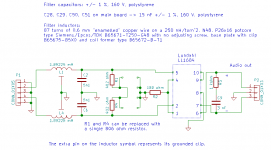
Attached are two suggested filter schematics with transformers for the raw-DSD version.
I will have some free time during the coming week so I will have a go at some PCBs for the reconstruction filter schematics Marcel provide in post #182.
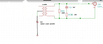
Marcel, I've decided to keep the output stage along the lines of your design and have dropped the idea of using the BCF valve stage, however, for my build I plan to use Lundahl LL1684 transformers instead of the Jensens; I already have some and will be using them in my Signalyst DSC2 decoder too (ppy's DSC 2.5.2 boards).
Do I need to make any changes to your filter schematics to use the LL1684s - I've attached the datasheet for info.
Oh, and I will be using the LL1684s to convert to balanced to SE output. I've attached a sketch of ppy's Signalyst DSC2 transformer configuration for the LL1684s.
Attachments
Hello Marcel,
is there a J109 SMD replacement (PMBFJ109 obsolete!)?
JP
The ON Semiconductor MMBFJ108 should be close enough and its status is active. (The status of their through-hole J109 is also active, but they have no MMBFJ109.)
Marcel, I've decided to keep the output stage along the lines of your design and have dropped the idea of using the BCF valve stage, however, for my build I plan to use Lundahl LL1684 transformers instead of the Jensens; I already have some and will be using them in my Signalyst DSC2 decoder too (ppy's DSC 2.5.2 boards).
Do I need to make any changes to your filter schematics to use the LL1684s - I've attached the datasheet for info.
Oh, and I will be using the LL1684s to convert to balanced to SE output. I've attached a sketch of ppy's Signalyst DSC2 transformer configuration for the LL1684s.
I would connect them as shown in the attachments. I've drawn the third-order variant (and only a single channel), but everything to the left of R1 and R4 simply stays as is, so you can figure out what the fifth-order version should look like.
You can connect the output to either a balanced or an unbalanced load, in the latter case the negative signal pin has to be grounded (preferably at the load). The same holds for the versions with Jensen transformers.
Attachments
Last edited:

Assuming you refer to the DSD-only variant: for the SMD parts near the inputs, I assume that everything is electrically small and can simply be connected to a buffer output with short wires.
The clock lines to the 74AHCT74s that run on -132 V/-137 V, clock5 and clockn5, are simple source-terminated microstrip lines. They are tapped of for the 74AHCT74 that is closest to the buffer, so this one will first see a 2.5 V step and then another 2.5 V step when the reflected wave gets back. It is a bit inelegant, but the timing should be OK no matter whether the flip-flop triggers on the first or the second step. The clock input of the 74AHCT74 is a Schmitt trigger input, so there is no risk of it oscillating either.
The clock lines clock and clockn to the E88CCs are source-terminated 42 ohm lines that are split into two 84 ohm lines in the middle between the E88CCs.
U9 and U10 are clocked on the opposite clock edge from U6, because otherwise there could be hold time violations due to the delay of U5 and U8 (or U7). clock5 and clockn5 are delayed with respect to clock and clockn, so that the data coming from the 74AHCT74 will always switch when the E88CC it drives has no tail current (RTZ action).
Does this answer the question?
Hello Marcel,
thank you for prompt answer, but my question was not clear enough, sorry.
Refering to the DSD-only variant, I2S logic generates only two differential clocks, CLKP/N and CLK5P/N. This two differential lines are to route to two different R and L DAC. If I´m routing a PC mainboard I would use special clock distribution IC (IDT or others).
JP

- Home
- Source & Line
- Digital Line Level
- Valve DAC from Linear Audio volume 13