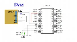
Not sure what you have tried with Arduino so far. Looks it it used 5v I2C, and where MS_bar and MDI set the I2C address, SCK is pin 7 and SDA is pin 13. MSEL = high for I2C.
There are various I2C libraries you can use. At least one library can scan the bus for you to find the address of any I2C devices present. You will need pullup resistors on SDA and SCL as I2C is an open collector bus.
There are also two ways of looking at and thinking about I2C bus addresses. Some libraries may only support one or the other addressing format, and some libraries support both. Addresses are 8-bits with the LSB setting the write and read addresses, or the address can be thought of as the 7 most significant bits with the extra bit-0 working as a read/write control bit.
For registered devices like this dac, there is a particular way that devices have to be communicated with.
First, the device write address has to be used and data sent in the first messge, the data being the register number to read or write.
If data is to be written, the 1st message will open a connection to the I2C slave device (dac) using the device write address and the data is the register to be selected. The 2nd message is sent to the same address and the data is written to the selected register
To perform a register read, the 1st message is written the write address of the dac and the data is the register to select (same as in the write case). However, to read, the 2nd message must be sent to the read address without first closing the connection. In that case some libraries will have a restart() function to write to a new address while keeping the connection established by the 1st message still open. After the register is selected and the read address of the device is sent out on the bus, the slave device writes out the selected register on the I2C bus for the master to read. Once the 2 messages are complete, then a stop message is sent to close the connection and release the I2C bus.
To illustrate using 8-bit addressing to read a register (using a library called, Soft I2C):
First there would need to be the include somewhere up at the top before setup():
#include <SoftI2CMaster.h>
The in the main loop for a read: loop():
// read and print value at register, RegNum
if (!i2c_start(0x90)) { // start transfer
Serial.println("*** Warning: I2C device busy ***");
Serial.println("*** Check seizure relay setting ***");
}
i2c_write(RegNum);
i2c_rep_start(0x91); // restart for reading -- would be (DevAdd + 1)
RegVal = i2c_read(1); // read one byte and send NAK to terminate
i2c_stop();
And a register write might look like:
i2c_start(0x90);
i2c_write(RegNum);
i2c_write(toRegB);
i2c_stop();
By the way, I think the Soft I2C comes with some example Arduino programs including the one that can scan the I2C bus for any devices present.
Hope this helps, or if not and you have a scope, you might try to see what SDA and SCL are doing when you try to read or write to a device on the bus.
Last edited:
Not sure what you have tried with Arduino so far. Looks it it used 5v I2C, and where MS_bar and MDI set the I2C address, SCK is pin 7 and SDA is pin 13. MSEL = high for I2C.
There are various I2C libraries you can use. At least one library can scan the bus for you to find the address of any I2C devices present. You will need pullup resistors on SDA and SCL as I2C is an open collector bus.
I have configured the circuit exactly like this. I’m running the I2C scanner code off of the Arduino website. The problem is that the library is based on slave devices having 7bit addresses. The address of this device is 8bit long and maybe that’s why it’s not being identified on the scanner?
I’ll try out the library that you suggested today.
I’m tying to build and Audio player using LPC1768 and PCM1795. I need to configure the DAC for taking 32bit I2S data as input. The default is set to 24bit. Can’t pro tip will be much appreciated.
Thank you.
7-bit vs 8-bit I2S addressing are just two different ways of looking at the same thing. Physically, the bit patterns are the same, the conceptual difference has to do with how the LSB in the 8-bit addressing word is interpreted. The LSB can be looked at as the last bit of an 8-bit address, or it can be looked at as being a R/W control bit that is not part of a 7-bit address.
If I2C communication still doesn't work with a different library, it might make sense to start looking at the I2C signals with a scope and or a cheap but effective for I2C ~ $10 logic analyzer. https://www.amazon.com/HiLetgo-Anal...8&s=gateway&sprefix=logic+anal,aps,204&sr=8-3
USB Logic Analyzer 24MHZ 8 Channel 12C UART SPI IIC CAN 1Wire Debug For ARM FPGA | eBay
Software that works with the cheap logic analyzers can decode I2C into hex format, making it much easier to read and to determine if I2C bus signals are behaving as they should in order to communicate with the dac chip.
Hi, I couldn't get that shipment on time so i had an angilent DSO in college and i probed the lines and this is what i got. It's sending out the correct 7 bit address and then attaching the correct read bit making it an 8 bit address. But i'm always receiving a NACK. I'm attaching the oscilloscope captured photo. I checked the SCL frequency. It's constant at 99KHz.
Attachments
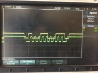
Hi, I couldn't get that shipment on time so i had an angilent DSO in college and i probed the lines and this is what i got. It's sending out the correct 7 bit address and then attaching the correct read bit making it an 8 bit address. But i'm always receiving a NACK. I'm attaching the oscilloscope captured photo. I checked the SCL frequency. It's constant at 99KHz.
That's not how to do it. You have to send out the 7-bit address on bits 7-1, and then add a 0 for bit-0. Exact same thing as for 8-bit addressing. The you send data next without releasing the bus. As the second part of the first message you send the second 8-bits containing the address of the register you want to read. That whole 16bit thing is actually one message, 8-bits of address and the r/w bit set to 0 for a write. The next 8 bits contains the hex or binary (same thing) register number.
Then also without dropping the bus you have to do a re-start to the 7-bit address with a 1 in bit-0 (the 8-bit read address part of the next 16-bit transaction). That means you are sending a read command to that address, Then the slave (dac chip) should send the selected register contents back in the next 8-bits according to the SCL clock still being generated by the master (arduino), which completes the second 8-bits of the full 16bit read transaction.
You won't get the first ack back until you have written to the write address and sent the register number (data to be written), that's one complete message consisting of 16-bits, the first 8 bits are the address including the r/w bit, and the second 8 bits is the register address that you wrote. After one good 16bit message is received by the dac is when you should get an ack
Last edited:
Okay. So I have to start the bus, Send the slave address(7bit add + 1R/W bit), then without dropping the bus, send the register address which makes it a total 16 bit long.
After which i can get an ACK.
Now That i have set the register index, I can start sending the slave address with a ' 1 ' on bit 0 indicating that I have to read the data, so the first 8 bits of the 16 bit transaction contains the address with read register and the slave will send the data in the next 8 bits of the 16 bit transaction.
I'll try this.
Thanks.
The second write, this time to the read address is technically a 'restart.' The reference here may be helpful: Repeated Start Condition - I2C Bus
Also, that latest bus specification can be found at: https://www.nxp.com/docs/en/user-guide/UM10204.pdf
Also, that latest bus specification can be found at: https://www.nxp.com/docs/en/user-guide/UM10204.pdf
Last edited:
- Status
- This old topic is closed. If you want to reopen this topic, contact a moderator using the "Report Post" button.
- Home
- Source & Line
- Digital Line Level
- pcm1796 i2c arduino uno wiring configuration