As I mentioned the Freedsp people have done a great job:- I thoroughly recommend their quick start guide for the FreeUSBi (which can be found here https://docs.google.com/document/d/1rKkCl3gyePwX15c3sjEIKP6Bb7CO77hgRAXtbYz5hA0/edit?usp=sharing ).
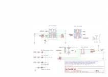
From that document I have copied their schematic (first enclosure)
The connections (from the cypress chip) that I have replicated are
1) Gnd (from P1.6)
2) Brd_Reset (from P1.15, with the limiting resistor)
3) USB_Pwr_On (from P4.20)
4) SDA (from P1.14)
5) SCL (from P1.13)
(The other connections, LEDs etc are nice, but optional)
Gnd is Gnd, I connected it to J3p4 on the Sure board and the level shifter
Brd_Reset goes to J3p9 via a 470 ohm
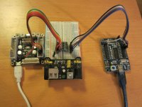
That leaves the circuitry around Q1 and Q2 on the FreeUSBi to bodge.
I used this level shifter
1PCS 5V to 3.3V Bi-Directional SPI I2C Logic Level Converter 4way Arduino | eBay
but there are lots out there
The second enclosure gives the schematic for the level shifter.
These are very similar to Q1 and Q2 in the FreeUSBi.
By connecting USB_PWR_ON (from cypressP4.20) to LV on the level shifter (and thence to ground through a 1meg resistor) the original circuit is largely duplicated.
I then feed scl and sda from the cypress into LV1 and LV2 and take them to the Sure board from HV1 and HV2. It seems to work, though I really ought to tie HV to the 3v3 on the Sure board.
From that document I have copied their schematic (first enclosure)
The connections (from the cypress chip) that I have replicated are
1) Gnd (from P1.6)
2) Brd_Reset (from P1.15, with the limiting resistor)
3) USB_Pwr_On (from P4.20)
4) SDA (from P1.14)
5) SCL (from P1.13)
(The other connections, LEDs etc are nice, but optional)
Gnd is Gnd, I connected it to J3p4 on the Sure board and the level shifter
Brd_Reset goes to J3p9 via a 470 ohm
That leaves the circuitry around Q1 and Q2 on the FreeUSBi to bodge.
I used this level shifter
1PCS 5V to 3.3V Bi-Directional SPI I2C Logic Level Converter 4way Arduino | eBay
but there are lots out there
The second enclosure gives the schematic for the level shifter.
These are very similar to Q1 and Q2 in the FreeUSBi.
By connecting USB_PWR_ON (from cypressP4.20) to LV on the level shifter (and thence to ground through a 1meg resistor) the original circuit is largely duplicated.
I then feed scl and sda from the cypress into LV1 and LV2 and take them to the Sure board from HV1 and HV2. It seems to work, though I really ought to tie HV to the 3v3 on the Sure board.
Attachments
Thank you for sharing your information,
I order the parts and will post later my experience.
I have already the USBI from Analog Devices and the MiniZ evaluation kit.
It works well.
I ordered one sample Sure board from the Sure store, it was delivered very quickly by DHL.
But it is impossible to program it with the USBI by making a six pin cable from the USBI 10 pin connector.
So I contacted Sure several times by skype and by email, but no reply.
The board is great and very affordable, it is a pity that there is absolutely no support. I don't know if the board works or not.
BR,
GB
I have it at home to...also recived the evaluation board...but have no idea where to start. The guy from Sure told me that you only need eval. board to connect it to comp and use sigma studio to program. If I understand correclty, you need to program your own program-interface with sigma studio...is that true?
It would be really great if anyone have an idea how to make this thing work.
It would be really great if anyone have an idea how to make this thing work.
GBDA,
Well you are ahead of me! I am mystified why the Sure board does not work with the USBi. For me, with the configuration I describe, Sigmastudio can read the EEPROM and the register set of the ADAU1701.
The next steps for me are:
1) Tie Self Boot to ground so that I can program from Sigma Studio direct into the ADAU1701 (rather than put boot code into the EEPROM)
2) And once I have stable code, tie WP to ground so that Sigma Studio can write to the EEPROM
Of course something may not go according to plan on one or both of these two steps!!
And I have still to build a standard frequency Mclk
Hormilo,
Not sure I can help, I am not sure of the difference between the evaluation and production Sure boards. As you can see from my posts, I certainly needed a USBi (as per GBDA), a FreeUSBi or a homebrew (as per my posts).
As a very rough guess, if you can see SCL and SDA on the silkscreening, you probably need one of the I2C interfaces noted above. Perhaps you could post a photo of the board?
The DSP board is working but not fully.
I bought the audio extension board too, connected to the DSP board with the supplied 10 pins cable.
Left audio is working but not right.
Pot4 seems to control left level
Pot3 seems to control high pass filter
Pot2 no action ?
Pot1 no action ?
Without any manual it is quiet frustrating ...
No free time before week end now, I will follow my experiment later.
See you
The crystal on my board is a 12.000Mhz and not a 12.288Mhz, making the whole thing run at a non standard frequency.
Yep--my board has the 12MHz crystal also. That's really strange.
A couple of other observations:
- The board is set up for 2V RMS input (18K resistors on input). This will result in an overall gain of .5. If you aren't going to provide jumpers to set the input level, it is probably better to set the input for 1V RMS, since that is the commercial standard. The 18K resistors are R7 and R8. They should be 8K for 1V input.
- The sub and headphone jack use the SGM4917 headphone amp. That chip has the charge-pump to generate the negative voltage needed to make the output ground referenced. It also results in higher output for the headphone and sub.
- There doesn't appear to be reconstruction filters on either board--at least, I haven't been able to account for the parts needed for the filter. If so, that's OK for most class D amps, but an inconvenience for some applications.
- The 10 pin connectors are labeled differently at the DSP board and I/O board for pins 6 and 7. The DSP board has OUTL2 and OUTR2, whereas the same pins on the I/O board are labeled AGND and SUB.
Neil,
Thanks for digging around on the input stage, I will need to take account of that. Those resistors are too small for old eyes like mine (without a magnifying glass .... and yes,I have the same values). I'll TRY and piggy back a 15k on each.
I don't have the RCA socket daughter board (difficult to get this side of the pond), So your observations are particularly useful. On my DSP silk screen OutR2 and OutL2 are pins 7&8 ??
Pure guess, but I presume C30 - C33 are the output caps, what reconstruction filters are you planning (not my area of expertise)? I hope the filter can just tack on after the caps, which look to be bulky dc blockers??? Sadly I am a retro amp freak, class D arrived around 20 years too late to shape my taste.
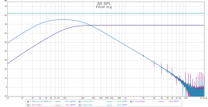
GB, As promised I have checked audio through my card. All channels function (I connected direct to the 10 way connector, because I do not have a daughter board).
Neil, As you predicted 6dB insertion loss.
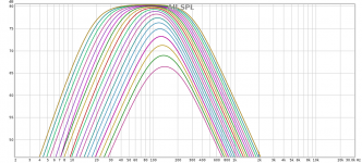
All, the shipped firmware is indeed a 2 way cross over. I have not had time to pot twiddle, the attached graph is as the card came out of the box. Traces are basically loop bypass (flat) and the two outputs (L/R channels pretty much identical). Dig those crazy resonances in the sub-woofer output .... good job that your woofer cannot reproduce HF eh
Neil, As you predicted 6dB insertion loss.
All, the shipped firmware is indeed a 2 way cross over. I have not had time to pot twiddle, the attached graph is as the card came out of the box. Traces are basically loop bypass (flat) and the two outputs (L/R channels pretty much identical). Dig those crazy resonances in the sub-woofer output .... good job that your woofer cannot reproduce HF eh
Attachments
I don't have the RCA socket daughter board (difficult to get this side of the pond), So your observations are particularly useful. On my DSP silk screen OutR2 and OutL2 are pins 7&8 ??.
Yes, but the I/O board silkscreen numbers the pins as 0 to 9, and I just used their numbers. So it would be pins 7 & 8 if you don't have the I/O board to go by.
Pure guess, but I presume C30 - C33 are the output caps, what reconstruction filters are you planning (not my area of expertise)? I hope the filter can just tack on after the caps, which look to be bulky dc blockers??? Sadly I am a retro amp freak, class D arrived around 20 years too late to shape my taste.
Yes, C30 - C33 appear to be the output caps. I measured about 2uF for C30 and verified that one side goes to the connector and the other side goes directly to a pin on the ADAU1701. So no reconstruction filter on the DSP board. You can get that value in the 0603 package with an X7R cap, so I assume that is what they are using.
ADI has a recommended passive reconstruction filter that uses 604 ohm resistors, and I can't find anything like that on the I/O board. Maybe they are there, but I can't find the components needed for that filter. Most of that "hash" you show in the FR plot is probably due to having no filter--it's definitely not on the DSP board.
Most of the "popular" class D amps show a lowpass filter in their block diagrams that would function as a reconstruction filter. So I don't think the filter is needed for most class D amps, although I've never seen a detailed description of those lowpass filters to know for sure. The ADAU1701 datasheet shows both a simple passive filter and a 3-pole active filter that they say may provide "better audio performance". The FreeDSP board uses the active filter.
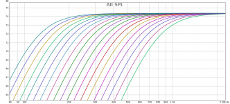
A brief update on the pots. I refer to them via the gpio number that they are connected to, because I am not sure there is an agreed numbering scheme. All data comes from measurement and sadly not a datasheet.
MP2 main channel volume (max is -6dB as per Neils observations)
MP3 main channel bass roll off (-12dB octave). 0V -3dB at 800Hz, max V (ie 3.3V) -3dB at 120Hz)
MP8 Sub woofer filter centred at 160Hz, 0V -3dB points are 80/240Hz, 3.3V-3dB points are 20/300Hz
MP9 Sub woofer gain, 0Von pot reduces output by 54dB below 3.3V value (which is around -2dB)
These are all rough readings to help people get started. The filter shapes are probably quantised, but I have not checked yet.
Neil, thanks for all that information. I'll look at the FreeDSP designs, so many thanks from me and my amplifier!
Hi,
I fully tested the DSP and audio boards today and finally they work !
For my project I need to load a new software. Now I have to find a solution to load the code from SigmaStudio to the EEPROM.
With an original AD USBI and with a 6 pins to 10 pins cable, it does not work.
I bought a Cypress CY7C68013A Mini board too.
Any help will be appreciated.
Thank you in advance
GB
For my project I need to load a new software. Now I have to find a solution to load the code from SigmaStudio to the EEPROM.
I'll probably have something that will work in about month. I have a project where I will be using the ASD software and an Arduino Redboard board to control the Sure DSP. The Redboard has the FDTI interface that ASD needs to communicate with the Arduino. The Arduino code responds to the commands from ASD to manage the ADAU1701 in real time (with selfboot disabled). ASD also has a routine to program the EEPROM with the SigmaStudio program, which is what you are looking for.
I haven't worked on ASD for quite a while, and it needs lots of updates. Also, I still need to migrate some more Arduino code for this board. I've been moving code that was written in 6801 assembler code to the Arduino, but there are still some more pieces left to bring over. One of those pieces is the EEPROM programmer.
There is an old version of ASD that you can play with at this URL:
http://www.audiodevelopers.com/Software/ASD/setup.exe
Edit: there is an explanation of how ASD interacts with SigmaStudio in the Help file for the "Control Hardware" module. Look for the "User Manual: SigmaStudio Tools". ASD is a full user interface for the ADAU1701 boards, and it only uses SigmaStudio to define the DSP architecture. This approach is consistent with the way ADI expected SigmaStudio to be used, IMHO. A lot of people seem to be trying to use SigmaStudio as an end-user interface, and that doesn't make any sense to me.
Last edited:
- Home
- Source & Line
- Digital Line Level
- New? Sure Electronics ADAU1701 Module