Hello,
I consider starting a project tha would basically use receive music from USB, apply DSP and Crossover management and output I2S or SPDIF fo feed 4 x Full Digital Amplifiers channels (here 2x FX-Audio D802 with SPDIF), using a STM32F7 Nucleo board.
The chips have a DSP instruction set. Those boards can address in a quite rich way multiple I2S and SPDIF, in a synchronized way. They can use a dedicated oscillator for the audio part and have dedicated audio PLL. Last, they are cheap. It seems to me a good basis for a low jitter system.
But, I'm a beginner here, I lack a lot of knowledge, and for those topics the devil is in the details...
Objective is to be at least better than what would be achieved on a Raspberry Pi on the I2S output (should not be too difficult), and ideally achieving 95% of the performance of the "reclocking" boards considered here (I know how the last 5% can be hard to achieve in many cases).
Any comment, warning and advice is warmly welcomed.
JMF
I dunno, but I have to say, that ST's site has absolutely dismal information architecture. I found the product pages for two Nucleo boards with chips in the STM32F7 family, but there is no clear path to the datasheets for the relevant MCUs.
Saving others the trouble it took:
Nucleo-f767zi board
stm32f767zi MCU
Nucleo-f746zg board
stm32f746zg MCU
Saving others the trouble it took:
Nucleo-f767zi board
stm32f767zi MCU
Nucleo-f746zg board
stm32f746zg MCU
I agree with you. Not easy to find the information, the applications, the reference data...
However, the platform looks to me promising. And (I do some advertising), if I didn't needed more power, I think that the extension board that plugs on top, with the 2x40W amplifier based on the STA350BW, with all the software provided by ST, would beed a try: full digita chain from the USB to tha amp. One single clock to manage DSP, I2S to amps, Amps.
http://www.st.com/content/st_com/en.../stm32-ode-translate-hw/x-nucleo-cca01m1.html
JMF
Hi,
I recognize that it is not the easiest path. And I discover that STM32 is not the easiest platform. However I must say that this platform draws my curiosity, and seems to provide many elements I was looking for to fit my (not so) specific needs: USB in (ideally Asynch) / DSP processing for crossover and EQ / several digital out for active multiamp system.
miniDSP is not so rich when you look for USB in and several digital outs (without using several products like USBstreamer). Their main products don't seem to support that, it is not open, and much more expensive.
BBB is an option, as it is the only other SBC with multiple output digital lines, but has limited CPU power and is more complex as of software set-up.
I have the feeling that simple STM32 program templates (2 ways, 3 ways) , to fill with your specific filtering in an easy way, would be very versatile and efficient, with a lot of potential for further improvement for development of testing tools.
Last it is an Hobby and an opportunity to learn about new things. This in fact brings me many years back with myself discovering computers and microprocessors like the 6502, Z80, 68000... So I mainly have to dig in old and forgotten knowledge and update all this.
This said, I would be happy to invest in something with real potential. If some "went there, found that..." shows that there are basic flaws that will reduce the performance, I would prefer spend my energy elsewhere (knowing the why).
I must say that I'm surprised not to see more projects using this product. Maybe it is that the main benefits are only when you look for a full digital chain, digital filtering and multi amplification which is not so common but seems to draw more and more interest.
JMF
Your idea is doable. But perhaps not super simple.
I implemented a two channel, two way, crossover in a pic32 device by:
- setting up a timer at an integer multiple of the system master clock, and also close to
- this drove read and write cycles on the ADC and DAC. These were inside an ISR, with the ISR being called on the timer hitting zero.
- getting the master clock and divisor at integer multiples is important to avoid odd phase jitter on the i2s signals
- this did fourth order XO, parametric a, time delay etc.
- All the DSP calls also occur inside the ISR, this
- ensures the DSP is all done inside the cycle
- makes you get the timing right! Too much code and it falls over!
- all user interface and housekeeping occurs outside the ISR so it is essentially run in whatever time is left over.
This works fine when driving both the ADC and DAC.
If you wanted to read in data from SPDIF, I reckon you would want to I
Plent some form of ASRC. I have not thought this through, I wonder if a simple linear ASRC would've good enough
- if you could use a counter (repurpose a timer on pic) to count clocks of the DPDIF frame after the DSP idea of frame timing, then you could do s pretty simple ASRC
There is an example and the C code somewhere in my blog. But for PIC...
Last edited:
I kind of expect you are correct. The only reason I did a PIC32 version was as an intellectual exercise, and a challenge to myself to learn to code all the filters etc.
Generic micro's don't make great DSPs. In fact the PIC32 implementation only really worked when I made the compiler use the PIC32 DSP instructions.
That said, for the $5odd that a PIC32 costs, I think it is brilliant. As a challenge. (I guess I am showing my age - when I started electronics as a hobby there wasn't even a concept of "DSP" or "microcontroller")
Considering the availability of proven XMOS hardware and community version developer tools, it might have intercepted the viability of pursuing any Cortex-M7 or generic micro based path.
Hi,
This is exactly one one the reasons why I posted this question: is the candidate OK ? Aren't there much better candidates?
I know the miniDSP range. I have identified several XMOS USB to I2S boards, but with no means to configure them.
What would be the alternative XMOS platform with community tools?
Best regards,
JM
Hello, I consider starting a project that would basically use receive music from USB, apply DSP and Crossover management and output I2S or SPDIF fo feed 4 x Full Digital Amplifiers channels (here 2x FX-Audio D802 with SPDIF), using a STM32F7 Nucleo board.
On a PIC32, I implemented a two channel, two way, crossover in a pic32 device by:
- setting up a timer at an integer multiple of the system master clock, and also close to
- this drove read and write cycles on the ADC and DAC. These were inside an ISR, with the ISR being called on the timer hitting zero.
- getting the master clock and divisor at integer multiples is important to avoid odd phase jitter on the i2s signals
- this did fourth order XO, parametric a, time delay etc.
- All the DSP calls also occur inside the ISR, this
- ensures the DSP is all done inside the cycle
- makes you get the timing right !
- but, to much code and it falls over!
- all user interface and housekeeping occurs outside the ISR so it is essentially run in whatever time is left over.
This works fine when driving both the ADC and DAC.
If you wanted to read in data from SPDIF, I reckon you would want some form of ASRC. I wonder if a simple linear ASRC would've good enough.
Considering the availability of proven XMOS hardware and community version developer tools, it might have intercepted the viability of pursuing any Cortex-M7 or generic micro based path.
Hello JMF, like you I'm asking myself why there are almost no audio projects basing on the STM32F4 or STM32F7.
Hello googlyone, like you I have considered relying on a PIC32, using "bare"metal" C language software for driving a stereo ADC on I2S and two stereo DACs on I2S, interrupted by an ISR routine in assembly language recurring at 44.1 kHz, in charge of the audio DSP. Actually there was also a SPDIF input, because the ADC and the DACs were contained in a Wolfson WM8580 multichannel codec, featuring a SPDIF receiver having a having a clock recovery PLL. I went discouraged by the PIC32, because each PIC32 generation has a different synchronous serial interface. Some are not buffered, some are buffered, and some (the latest ones) feature an "audio mode" bit enabling to attain a I2S functionality. It was not clear to me, what chip has what. Then came the PIC32MZ, and the new software development environment. I found myself completely lost.
I then looked to the ARM Cortex-M4.
The STM32F3 and STM32F4 range looked promising.
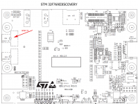
The STM32F4DISCOVERY, featuring the STM32F407VGT6 chip featuring I2S support and an audio clock PLL, was my first "starter kit".
Then came tjaekel : STMF4 Discovery USB Sound Card
He managed to program the STM32F4 Discovery (starter kit), as 2-channel USB sound card.
I went delighted when STM introduced the STM372xx and STM373xx, that are Cortex-M4 chips, featuring 3 x I2S. The match with a WM8580 6-channel codec looked perfect.
I went delighted again when STM intriduced the STM427xx and STM429xx, that are Cortex-M4 chips, featuring not only 3 x I2S, but also 1 x SAI supporting TDM.
I went delighted again when STM introduced the STMF7 range, kind of STM427xx and STM429xx with twice the processing power, and even more digital audio peripherals like the SPDIF-in now.
The fact that those chips are available as inexpensive Nucleo-64 or Nucleo-144 "starter kits" adds massive attraction !
Then came tjaekel again : STM32F7 Discovery Sound Card
He managed to program the STM32F7 Discovery (starter kit), as 2-channel USB sound card.
Setting up a STM32F7 software development environment is not a trivial task.
There are so many different.
Why not try the "genuine one" ? This is "Sytem Workbenck for STM32" from STM. I know nothing about it.
User feedback would be appreciated.
Configuring the clocks, peripheral and pinout of a STM32F7 chip is not a trivial task, event with the help of STMCubeF7.
Anyway, the SPDIF-in of the STM32F7 is an asynchronous device, writing audio samples into memory, on a frame-to-frame basis, without concern about clock recovery and jitter.
JMF, please have a look to the WM8580 chip.
The SPDIF-in of a WM8580 is in charge of recovering the audio clock, using a PLL in hardware, generating a high quality audio clock to be considered as master audio clock, and to be reused as such, for clocking the DACs.
Relying on a WM8580, the STM32F7 can remain asynchronous, without any concern about clock recovery and jitter. THis way, the STM32F7 only sees a hardware interrupt recurring at 44.1 kHz.
So, at this stage, at the bottom of the learning curve, I think it is advisable to start with a WM8580 as audio hub, and gradually add complexity :
Stage 1 : hardware : design a STM32F7 Nucleo-144 "shield" hosting a WM8580
Stage 2 : software : analog-in (the ADC of the WM8580), and up to 6 audio channels-out (the DACs of the WM8580). The WM8580 quartz is the audio master clock. It must be a 256 x 44.1 kHz = 11289.6 kHz quartz. Beware of a 12000 kHz quartz requiring some PLL to operate, that will degrade the audio master clock.
Stage 3 : software : SPDIF-in instead of analog-in. The WM8580 SPDIF clock recovery PLL is the audio master clock. Make sure you have the gear that's required for measuring the recovered clock jitter, on the 44.1 kHz signal, on the bitclock signal, and on the MCLK signal. Compare this to Stage 2, where the WM8580 11289.6 kHz quartz is the audio master clock.
Stage 4 : hardware : design a STM32F7 Nucleo-144 "shield" hosting I2S-input power amplifiers like STA350 or TDA7801 or TDA7802, up to six channels, such "shield" coming in parallel with the WM8580 "shield".
Stage 5 : software : let Stage 1, 2, and 3 operate with the WM8580 "shield"
Stage 6 : software : try relying on the STM32F7 SPDIF receiver as audio input, and measure the recovered clock quality, each time you conceive an apply a software method dealing with the audio clock recovery - this is going to take a lot of time and effort.
Stage 7 : software : get inspiration from tjaekel, programming the STM32F7 as 2-channel USB sound card, preferably in the Async USB audio modality.
Those seven stages, are the seven intellectual challenges that you'll be facing.
At this moment, I am highly focusing on the STM32F7, because it should have enough processing power for running six 1024-tap FIR filters recurring at 44.1 kHz, with a 32-bit precision. Consider 6 x 1024 x 44100 = 271 Mips. By the way, for obtaining the maximum throughput, I'm curious to know if it is required to unroll the do-loop of the FIR filters routines, written in assembly. There you will eventually see the ugly drawback of relying on a generic microprocessor, duly equipped with a one-cycle 32-bit precision Multiply-and-Accumulate instruction. This is to compare with a "real" DSP processor featuring a zero-overhead loop arrangement like the DSP56K (Motorola), twenty years ago.
There you will eventually realize that nowadays XMOS processors may be really able, and recommendable.
Why relying on FIR filters ?
Well, it may not be obvious for everybody. Let me explain.
Provided you know your target acoustic transfer function, and you know (because of having measured it) the acoustic transfer function of your bare speaker drivers, you know what's your required correction function, for each speaker driver, in amplitude and in phase.
Doesn't this trigger something in your mind ?
Do an inverse DFT of your required correction function, for a particular speaker driver. This is the impulse response of your required correction function. And guess what : such impulse response is the coefficient list of the FIR filter materializing it.
Do you get me ?
So, provided that you specify your target acoustic transfer function as a 1024-FFT data set (amplitude, phase), and provided that you carry your bare speakers measurements as 1024-FFT data sets (amplitude, phase), by applying an inverse FFT of the required correction (amplitude, phase), you'll end up knowing the coefficients of the required 1024-tap FIR filters. Easy as 1-2-3.
I consider as negligible, what's regarding the required processing power, some other bells and whistles like a global equalizer, IIR BiQuad based.
Say you add a 4th-order "Linkwitz Transform" using two IIR BiQuads in cascade, for making sure that the deep bass goes straight and extended, even in case of a native 4th-order bass-reflex response.
Say you add four IIR BiQuads in cascade for addressing phenomenons like speaker placement effects.
Say you add four IIR BiQuads in cascade as Butterworth highpass filter (Fc adjustable from 15 Hz to 150 Hz) as protection.
Anyway, here is the intellectual challenge #8.
The STM32F7 "shield" should embed the required hardware, for carrying out all measurement sessions for setting up a 3-way speaker. In other words, for being consistent and for getting recognition, your system needs to be perceived as a one-stop-shop.
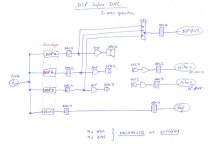
Consider the attached .jpg file.
You need 4-channel audio-in, and 4-channel audio-out.
An inexpensive STM32F7 Nucleo "shield' can handle this, embedding a quartz, two stereo ADCs on I2S-in and two stereo DACs on I2S-out.
Or possibly, preferably, your stereo 3-way crossover "shield" may feature 4-channel analog-in, instead of the classic 2-channel analog-in.
During the measurement session, the USB of the STM32F7 serves as data exchange (not audio this time) with a PC or a tablet executing a webpage, allowing the user to specify the target acoustic transfer function, and to watch curves like :
- the target acoustic transfer function, as specified by the user (does't fluctuate)
- the bare speaker transfer function (fluctuating)
- the required correction function (fluctuating)
- the transfer function that's resulting after the correction (fluctuating)
Up to 23 ms are taken by grabbing the 1024 audio samples data.
The USB takes some time, conveying the 4 channels-in and the 4 channels-out, not as audio, but as bulk data, say 50 ms.
The PC or tablet takes some time to FFT-process them, display them, compare them, display the comparison, inverse-FFT the comparison and update the 1024-tap filter coefficients, say 100 ms.
Comes the time to send the updated 1024-tap FIR filter coefficients as bulk data over USB, say 20 ms.
Which means that another cycle can start.
The minimum cycle time would be 23 ms + 50 ms + 100 ms + 20 ms = 193 ms.
We may thus hope that the curves get refreshed every 200 ms, worst case.
That's very good indeed.
After a while, thanks to a user-ajustable time-domain averaging of the data sets, the curves don't fluctuate much.
At any moment, the user can press a "store as ..." button, for putting up the actual corrections into a memory labelled "subwoofer", "woofer", "medium", or "tweeter". There can be several banks, for comparing different approaches.
After the measurements are made, after that several banks have been filled with meaningful data, the user asks the STM32F7 to exit the measurement modality.
The STM32F7 remains connected, and asks what bank to load.
The user can load a bank, listen to the result, load another bank, listen again to the result, etc.
After deciding what bank gives the best result, comes the possibility to "flash" such bank into the STM32F7 memory.
This way, each time the STM32F7 wakes up, it grabs the data that's in his "flash" memory, and it operates as standalone stereo 3-way crossover, not needing a USB connection, not needing a PC or a tablet.
Meanwhile, as soon as you connect a PC or a tablet on USB, the STM32F7 points to the web-based interface, and gets ready for another workbench session.
JMF, I hope that you have the required endurance, for succeeding. Your success is going to bring a lot of headroom, and fresh air, to the DIY Audio community. Not to say the level of expertise you will gain, kind of intellectual satisfaction. I'll help you, whenever you want.
Regards,
Steph
Attachments
Last edited:
The cherry on pie, is that most of the stuff that's done inside the PC (or tablet) can remain the same, in case such PC gets connected on 4 channel-in audio and 4 channel-out USB soundcard, like a MAYA44USB or a U-MIX44. This is the reason why on my diagram, you can read the name of those USB soundcards.
Now, guess what can happen if you tweak the STM32F7 software, for making the STM32F7 board appear as a high quality USB sound card featuring 4 channel audio-in, and 6 channel audio-out.
It will sell not only as a stand-alone stereo 3-way crossover, but also as PC-based stereo 3-way crossover, and it will be the sole and only one of its kind, because of embedding the 4 channel audio-in that are absolutely required for setting up a proper speaker workbench, fully integrated.
I guess you know the difficulty of relying on a PC or Home-Theater PC for implementing a crossover. You need to tell the PC, also acting as audio source, that the new "by default" audio device is a stereo (and stereo only) ASIO sink.
Your crossover operates as a VST, inside a VST host.
The 6-channel audio hardware (actually, your STM32F7 board) gets therefore driven by ASIO.
Do not forget the return path, consisting on the 4-channel input. They need to be treated the same way, also under ASIO.
By relying on a PC-class CPU for executing the six FIR filters, one can try 2048-tap or 4096-tap FIR filters.
Currently, I'm practicing the PC-based speaker workbench (and also crossover) using a Windows PC, Flowstone (I wrote several Flowtone apps), and a MAYA44USB soundcard. You can taste the beginning of it here :
Speaker Lab
WinXP directly driving two 4-way active speakers
Cheers,
Steph
From what's above, each cycle produces a new correction FIR filter.
One can apply averaging for smoothing the data, albeit smoothing must be taken for what it is, a simple way to neutralize uncorrelated errors. By averaging or IIR-lowpass-filtering hundreds of data frames, you'll end up with a pretty usable result, quite spectacular indeed. Been there, done this, look the "Speaker Lab" weblink in my previous post.
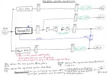
Now, look what's happening if you make the effort of adding one ADC and one DAC in the workbench.
See the attached .jpeg.
The new branch at the bottom, is the "Plant" branch, part of a Widrow-Hoff adaptive filter arrangement driven by the LMS algorithm, supposed to converge.
In such arrangement, the adaptive filter is the FIR filter that we require, for persuading the speaker driver, to behave as we want. The blue arrow indicates that the adaptive FIR filter gets updated by the LMS algorithm, which is a time-domain algorithm. It consumes less computing power than the FFT method and inverse-FFT method.
In such arrangement, the "Plant FIR" at the bottom is the impulse response of the Bode plot that you want to see, after the speaker has received the correction, this is thus the "ideal" impulse response, the acoustic impulse response that you are targeting, thanks to the speaker receiving the required correction. This is what I have written in red, on the .jpg. This is the exact same dataset, as the inverse-FFT of the target acoustic transfer function, as specified by the user. This is fixed, permanent data. There is thus nothing new to calculate.
I have not said that such LMS arrangement will converge.
Look the elephant in the room.
The LMS is a simple, all time-domain, FIR filter governor.
Unfortunately, we introduce a significant delay between the FIR filter that's governed, and the governor. In our case, the governor is the difference between the "Plant" signal and the "Mic" signal. The corrective coefficients vector that gets continuously issued by the LMS will land and stitch at a wrong position (index) in the FIR filter structure, much too late.
The LMS has little chance to converge, because of this !
Do you agree ?
Is there a known workaround, other than a time-machine ?
Is there scientific literature, telling what is the LMS convergence degradation and error, in function of the overall latency ?
I should take some time, trying the LMS method using a Behringer UCA202 soundcard, and a brand new Flowstone app derived from my Flowstone "Speaker Lab" app. I never took the time, because I think this is due to fail. Indeed, relying on a Windows PC and a Behringer UCA202 soundcard, the total latency may be as high as 200 ms !
On the other hand, relying on a STM32F7 and some particular audiophile ADCs and DACs advertised as "low latency", the total latency may be as low as 365 µs in case one obeys the rule of programming "bare metal" and having the DSP routine written in assembly, running in an interrupt service routine recurring at 44.1 kHz. No "audio buffer" thus. Worth trying maybe. Those "low latency" audiophile ADCs and DACs may remain affordable, nowadays.
Worst case scenario is that we require a sub-100 µs latency, in which case we need "flash" and "not pipelined" data converters. Are there such "flash" and "not pipelined" data converters available, and at which price ? Can they operate at 44.1 kHz, while featuring at least a true 14-bit resolution ? Do we need to oversample them for getting a kind of protection over high frequency aliasing ? They would come as an extra-cost, and consume one or two SPI ports on the CPU. They would solely be used while exercising the LMS convergence. I'm looking forward to your comments and suggestions.
Now, from all what's above, don't you think one can arrange some "incremental" frequency-domain method ?
Let us revert back to the frequency-domain method explained in my previous post.
The "Mic/Ref" Bode plot describes the actual speaker behavior after he receives the FIR-filter correction.
The "Plant" Bode plot describes ideal speaker behavior after he receives the FIR-filter correction.
The difference between the two Bode plots, describes the "incremental" correction that is required, for the "actual" becoming closer to the "ideal".
The first idea that's coming to my mind, is to scale such dataset (multiply it by a number comprised between 0.0 and 1.0, in real/imaginary), and to IIR-lowpass-filter the datasets (kind of improved averaging), for putting the IIR-lowpass-filtered dataset, atop the current dataset, as fine tuning, as way to converge. After taking into account each new real/imaginary dataset, the updated real/imaginary dataset will twist less, and slower. This is something I'd love to try. We gain more control than just averaging or IIR-filtering a set of successive but not so related FIR filters. This time, I can isolate the net contributions, and scale them before averaging or IIR-filtering them.
Quite interesting, this is something worth trying using a PC, a brand new Flowstone app derived from my "Speaker Lab" Flowstone app, and a MAYA44USB soundcard featuring the required 2 audio-out and 3 audio-in.
Best Regards,
Steph
One can apply averaging for smoothing the data, albeit smoothing must be taken for what it is, a simple way to neutralize uncorrelated errors. By averaging or IIR-lowpass-filtering hundreds of data frames, you'll end up with a pretty usable result, quite spectacular indeed. Been there, done this, look the "Speaker Lab" weblink in my previous post.
Now, look what's happening if you make the effort of adding one ADC and one DAC in the workbench.
See the attached .jpeg.
The new branch at the bottom, is the "Plant" branch, part of a Widrow-Hoff adaptive filter arrangement driven by the LMS algorithm, supposed to converge.
In such arrangement, the adaptive filter is the FIR filter that we require, for persuading the speaker driver, to behave as we want. The blue arrow indicates that the adaptive FIR filter gets updated by the LMS algorithm, which is a time-domain algorithm. It consumes less computing power than the FFT method and inverse-FFT method.
In such arrangement, the "Plant FIR" at the bottom is the impulse response of the Bode plot that you want to see, after the speaker has received the correction, this is thus the "ideal" impulse response, the acoustic impulse response that you are targeting, thanks to the speaker receiving the required correction. This is what I have written in red, on the .jpg. This is the exact same dataset, as the inverse-FFT of the target acoustic transfer function, as specified by the user. This is fixed, permanent data. There is thus nothing new to calculate.
I have not said that such LMS arrangement will converge.
Look the elephant in the room.
The LMS is a simple, all time-domain, FIR filter governor.
Unfortunately, we introduce a significant delay between the FIR filter that's governed, and the governor. In our case, the governor is the difference between the "Plant" signal and the "Mic" signal. The corrective coefficients vector that gets continuously issued by the LMS will land and stitch at a wrong position (index) in the FIR filter structure, much too late.
The LMS has little chance to converge, because of this !
Do you agree ?
Is there a known workaround, other than a time-machine ?
Is there scientific literature, telling what is the LMS convergence degradation and error, in function of the overall latency ?
I should take some time, trying the LMS method using a Behringer UCA202 soundcard, and a brand new Flowstone app derived from my Flowstone "Speaker Lab" app. I never took the time, because I think this is due to fail. Indeed, relying on a Windows PC and a Behringer UCA202 soundcard, the total latency may be as high as 200 ms !
On the other hand, relying on a STM32F7 and some particular audiophile ADCs and DACs advertised as "low latency", the total latency may be as low as 365 µs in case one obeys the rule of programming "bare metal" and having the DSP routine written in assembly, running in an interrupt service routine recurring at 44.1 kHz. No "audio buffer" thus. Worth trying maybe. Those "low latency" audiophile ADCs and DACs may remain affordable, nowadays.
Worst case scenario is that we require a sub-100 µs latency, in which case we need "flash" and "not pipelined" data converters. Are there such "flash" and "not pipelined" data converters available, and at which price ? Can they operate at 44.1 kHz, while featuring at least a true 14-bit resolution ? Do we need to oversample them for getting a kind of protection over high frequency aliasing ? They would come as an extra-cost, and consume one or two SPI ports on the CPU. They would solely be used while exercising the LMS convergence. I'm looking forward to your comments and suggestions.
Now, from all what's above, don't you think one can arrange some "incremental" frequency-domain method ?
Let us revert back to the frequency-domain method explained in my previous post.
The "Mic/Ref" Bode plot describes the actual speaker behavior after he receives the FIR-filter correction.
The "Plant" Bode plot describes ideal speaker behavior after he receives the FIR-filter correction.
The difference between the two Bode plots, describes the "incremental" correction that is required, for the "actual" becoming closer to the "ideal".
The first idea that's coming to my mind, is to scale such dataset (multiply it by a number comprised between 0.0 and 1.0, in real/imaginary), and to IIR-lowpass-filter the datasets (kind of improved averaging), for putting the IIR-lowpass-filtered dataset, atop the current dataset, as fine tuning, as way to converge. After taking into account each new real/imaginary dataset, the updated real/imaginary dataset will twist less, and slower. This is something I'd love to try. We gain more control than just averaging or IIR-filtering a set of successive but not so related FIR filters. This time, I can isolate the net contributions, and scale them before averaging or IIR-filtering them.
Quite interesting, this is something worth trying using a PC, a brand new Flowstone app derived from my "Speaker Lab" Flowstone app, and a MAYA44USB soundcard featuring the required 2 audio-out and 3 audio-in.
Best Regards,
Steph
Attachments
Last edited:
Hi,
I have endurance and a much less ambitious objective.
Set-up a configuration on a stm32F7 Nucleo board that:
- will input USB stereo file (interface to standard PC feature),
- perform the DSP crossover/Eq with IIR filters using the CMIS DSP libs,
- output on two synccronized SPDIF implemented in the stm32 SAI.
I will share with the community, if I succeed, a source template, taking into account all the USB Input and SPIF/I2S Output part. User would just have to fill the DSP sequence of filters. I'll also share the schematics for the SPDIF output from the nucleo board.
I don't know about hardware design. I want to streamline the thing, so I won't use additional harware like the WM8580. I won't consider ADC/DAC as I want to stay digital and that it is what I don't easily find.
By the way, ST sells a really nice cape with a STA350, and all the software to control it. At abou 35€ it seems difficult to beat the price/features ratio.
Have you looked at the nucleo F7 clock structure to manage 44.1 or 48Kz with good accuracy (read from USB and write to SPDIF)?
Best regards,
JMF
Last edited:
Hi JMF11,
unfortunately, tjaekel has not yet resolved an annoying bug, showing when the STM32F7 is operating as USB soundcard. This is related to the way the STM32F7 separates the CPU clock domain (must be related to the 48 MHz USB frequency), and the audio clock domain (should be a quartz at N x the sampling frequency, considered as audio clock master).
Check it here : STM32F7 Discovery Sound Card
As starting point, we must configure the main STM32F7 clocks, for getting a precise 48 kHz USB clock, and a close to 200 MHz core clock. For the sake of precision and stability, we better base on a 16 MHz quartz, than the internal 16 MHz RC oscillator. We pay attention to the bus clocks, not pushing them to the limits, in order to decrease the energy consumption, hence decreasing the electromagnetic pollution and thermal stress also.
The STM32F7 will be in charge of the USB audio buffer, say 1024 audio samples, explicitly requesting audio samples from the PC, when the USB audio buffer becomes close to empty. This is the asynchronous audio USB modality. Such modality guarantees that no clash can happen, between the quartz that's in the PC (or CD player of the PC), and the quartz that's operating as audio clock master, on the STM32F7 board.
Such STM32F7 audio clock quartz is distinct, and exhibits another frequency than the STM32F7 16 MHz CPU quartz.
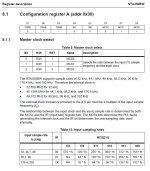
Most of the time, a 256 x 48 kHz = 12,288 kHz quartz oscillator gets hooked on the STM32F7 Audio Clock Input pin, each time there is question of a high quality I2S transmit or receive at 48 kHz.
Instead, using the STM32CubeMX utility, I tried hooking a 64 x 48 kHz = 3,072 kHz quartz oscillator on the STMF7 audio clock input. That's not good for the I2S peripherals. We don't care, as this time we don't use the I2S stuff.
Instead, we will use the SAI stuff.
The STM32CubeMX utility shows that the SAI1 works perfect, as SPDIF master transmit, at the 48 kHz sampling frequency, when selecting such 3,072 kHz clock as SAI1 clock source. I know it looks weird !
From such (weird) starting point, we need to exploit the 48 kHz interrupts generated by the SAI. Luckily, probably, the SAI generates an interrupt, each time his TX register gets empty. It does so for telling us that we may write a new stereo pair in his TX buffer, in case we want the SPDIF audio transmission to continue. Our software can take a few microseconds before actually doing this, because the SAI only start a new transmission, not as soon as we "hit the enter key", but only when the next 48 kHz "tick" (hardware defined) occurs. This way, the SAI SPDIF transmission remains free of jitter.
Consequently, the rate at which we consume audio data inside the USB audio buffer, is governed by the "high quality" local audio clock, in other words, the 3,072 kHz quartz oscillator. That's perfect.
As explained above, as soon as the USB audio buffer tends to go dry, the STM32F7 must ask over USB, to the audio source, a new packet of audio data.
In theory, you should be happy with the result.
The SAI will send a SPDIF stream, at the exact nominal 48 kHz frequency. There will be no customers complaining about their SPDIF receivers, being unable to lock on your SPDIF transmitter.
The SAI will transmit with minimal jitter, knowing that the SPDIF principle always introduces jitter, and knowing that any decent SPDIF receiver, must rely on an analog PLL, or sophisticated digital PLL, or ASRC for smoothing the recovered audio clock.
Attached is a screen hardcopy of the STM32CubeMX utility.
Regards,
Steph
unfortunately, tjaekel has not yet resolved an annoying bug, showing when the STM32F7 is operating as USB soundcard. This is related to the way the STM32F7 separates the CPU clock domain (must be related to the 48 MHz USB frequency), and the audio clock domain (should be a quartz at N x the sampling frequency, considered as audio clock master).
Check it here : STM32F7 Discovery Sound Card
As starting point, we must configure the main STM32F7 clocks, for getting a precise 48 kHz USB clock, and a close to 200 MHz core clock. For the sake of precision and stability, we better base on a 16 MHz quartz, than the internal 16 MHz RC oscillator. We pay attention to the bus clocks, not pushing them to the limits, in order to decrease the energy consumption, hence decreasing the electromagnetic pollution and thermal stress also.
The STM32F7 will be in charge of the USB audio buffer, say 1024 audio samples, explicitly requesting audio samples from the PC, when the USB audio buffer becomes close to empty. This is the asynchronous audio USB modality. Such modality guarantees that no clash can happen, between the quartz that's in the PC (or CD player of the PC), and the quartz that's operating as audio clock master, on the STM32F7 board.
Such STM32F7 audio clock quartz is distinct, and exhibits another frequency than the STM32F7 16 MHz CPU quartz.
Most of the time, a 256 x 48 kHz = 12,288 kHz quartz oscillator gets hooked on the STM32F7 Audio Clock Input pin, each time there is question of a high quality I2S transmit or receive at 48 kHz.
Instead, using the STM32CubeMX utility, I tried hooking a 64 x 48 kHz = 3,072 kHz quartz oscillator on the STMF7 audio clock input. That's not good for the I2S peripherals. We don't care, as this time we don't use the I2S stuff.
Instead, we will use the SAI stuff.
The STM32CubeMX utility shows that the SAI1 works perfect, as SPDIF master transmit, at the 48 kHz sampling frequency, when selecting such 3,072 kHz clock as SAI1 clock source. I know it looks weird !
From such (weird) starting point, we need to exploit the 48 kHz interrupts generated by the SAI. Luckily, probably, the SAI generates an interrupt, each time his TX register gets empty. It does so for telling us that we may write a new stereo pair in his TX buffer, in case we want the SPDIF audio transmission to continue. Our software can take a few microseconds before actually doing this, because the SAI only start a new transmission, not as soon as we "hit the enter key", but only when the next 48 kHz "tick" (hardware defined) occurs. This way, the SAI SPDIF transmission remains free of jitter.
Consequently, the rate at which we consume audio data inside the USB audio buffer, is governed by the "high quality" local audio clock, in other words, the 3,072 kHz quartz oscillator. That's perfect.
As explained above, as soon as the USB audio buffer tends to go dry, the STM32F7 must ask over USB, to the audio source, a new packet of audio data.
In theory, you should be happy with the result.
The SAI will send a SPDIF stream, at the exact nominal 48 kHz frequency. There will be no customers complaining about their SPDIF receivers, being unable to lock on your SPDIF transmitter.
The SAI will transmit with minimal jitter, knowing that the SPDIF principle always introduces jitter, and knowing that any decent SPDIF receiver, must rely on an analog PLL, or sophisticated digital PLL, or ASRC for smoothing the recovered audio clock.
Attached is a screen hardcopy of the STM32CubeMX utility.
Regards,
Steph
Attachments
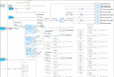
I'm attaching a .zip containing the .ioc projects that I saved using the STM32CubeMX utility.
For 48 kHz audio :
The SAI configured as I2S protocol, require a 256 x Fs = 12,288 kHz oscillator on the STM32F7 Audio Clock Input.
The SAI configured as SPDIFTX protocol, require a 64 x Fs = 3,072 kHz oscillator on the STM32F7 Audio Clock Input.
For 44.1 kHz audio :
The SAI configured as I2S protocol, require a 256 x Fs = 11,289.6 kHz oscillator on the STM32F7 Audio Clock Input.
The SAI configured as SPDIFTX protocol, require a 64 x Fs = 2,822.4 kHz oscillator on the STM32F7 Audio Clock Input.
That's weird, isn't ?
Attachments
Hi JMF11,
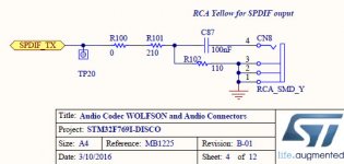
You may be not be aware, June 30th 2016, the STM32 Evaluation Tools forum replied to your query about the SPDIF-TX protocol on SAI.
Your query shows in the list here : https://my.st.com/public/STe2ecommunities/mcu/Lists/STM32Discovery/AllItems.aspx
The SPDIF-TX protocol on SAI is in the STM 32F769IDISCOVERY.
It relies on SAI2/SAIA (labelled SAI2_SD_A in the STM32CubeMX utility), located on the PD11 pin, labelled as SPDIF_TX on the schematic.
I'm attaching the detailed info.
Consequently, if you find exemplative software from STM (and I guess there may be in the STM 32F769IDISCOVERY documentation), remember that it is targeting SAI2/SAIA (PD11 pin).
Is it feasible to setup the STM32F7 this way :
SAI1/SAIA : SPDIF-TX protocol
SAI1/SAIB : SPDIF-TX protocol
SAI2/SAIA : SPDIF-TX protocol
SAI2/SAIB : SPDIF-TX protocol
in a well synchronized manner,
for outputting no less than 8 audio channels ?
How to control and synchronize the listening volumes ?
Let's go back to your idea of outputting 4 audio channels, for setting up a stereo 2-way configuration.
In your post, you wrote that you are going to rely on two FX-Audio D802 digital amplifiers, featuring a SPDIF-in and a remote control.
They can be seen here : FX-AUDIO D802 Amplificateur numrique Class D STA326 stro 2x 50W / 8 Ohm - Audiophonics
Say you allocate amp-1 for the left 2-way speaker.
Say you allocate amp-2 for the right 2-way speaker.
Can you setup the two amps, in such a way that they obey the same remote volume control ?
The remote control is infrared, hence directional, and that's maybe an issue.
Is it incremental control, or is it absolute control ?
I'm asking this, for knowing if the four volumes will remain synchronized whatever happens.
Worst case would be that you need to operate both remote controls, in case they have different ID codes.
Have you tried ?
Back in 1994, Philips made the DSS940 and DSS930 speakers.
Both were 2-way speakers featuring a SPDIF-in, and a digital crossover inside relying on a Mororola DSP56K. The digital crossover relied both on IIR BiQuads, and a FIR filter. If I remember, the crossover frequency was 3400 Hz, and the FIR filter had 30 taps. It was full complementary, phase synchronous, and phase linear. In other words, ideal.
In order to manage the listening volume, there was a dedicated preamp, the DSC950.
The listening volume was not made by scaling the audio data over SPDIF.
The listening volume was not made by a radio remote control sending absolute data to both speakers.
The listening volume was made by superimposing a low frequency modulation on the SPDIF. The SPDIF was thus DC-coupled. No isolation transformer allowed. They could have relied on optical isolation, but they did't. The low frequency modulation was the voltage coming from a 1200 baud USART, in asynchronous mode. They managed to make it bidirectional (half duplex of course). I have the schematics. I would not follow such path as nowadays, most SPDIF receivers feature an isolation transformer, something that's definitively required for avoiding ground loops.
I can easily understand that you prefer relying on SPDIF cabling, because of the allowed length of SPDIF cables, quite long, say 5 meter.
This allows each power amplifier to be located close to its speaker.
This is indeed perfect, provided that the volume control works flawlessly.
You commented, in a positive way, about the STA350 amplifiers from STM, having a I2S input. I guess you know they require a I2C bus for determining the listening volume info. The STA326 is quite the same. And there is one in the the FX-Audio D802 amplifier !
Look the TDA7801 and TDA7802. They also have a I2S input. They require a I2C bus for selecting the gain (only a 4-level choice) and thus, they rely on the audio data scaling.
I can easily understand that you perceive the advantage of suppressing SPDIF as intermediate medium.
I can easily understand that you would like to try such approach also.
This time, the power amplifiers must stay as close as possible to the STM32F7 board.
It is going to be a crowded shoe-box, considering the STM32F7 board, power amplifiers, remote control receiver, some heatsinking maybe, and the power supply.
It is going to require 4 lengths of thick speaker cabling.
The WAF (wife acceptance factor) is not going to be good.
Just in case you want to try such digital crossover directly feeding I2S-input power amplifiers, remember that a I2C bus is always required, as control bus, for governing the listening volumes.
An interesting approach would be that you analyze the data sent by the FX-Audio D802 remote control, in order such remote control to be reused.
You would hack a FX-Audio D802 amplifier, connecting its remote control receiver to the STM32F7. The remote control receiver is the small 3-pin device, black, next to the volume pot of the FX-Audio D802. This way the STM32F7 will learn the codes sent by the remote control. You need the STM32F7 to understand those codes, and reformat them, and broadcast them on the I2C bus connecting to the STA350, STA326, or TDA7801, or TDA7802.
So you see, the STM32F7 can possibly operate as stereo 2-way digital crossover in conjunction with :
- two FX-Audio D802 SPDIF-in power amplifiers, unmodified (hoping there is no issue with the volume control)
- a couple of STA326/350 I2S-in (class D) power amplifiers, with a proper remote volume control
- a couple of TDA7801/7802 I2S-in (class AB) power amplifiers, with a proper remote volume control
Next stage would consist of hacking the FX-Audio D802 amplifier a little bit further.
First of all, the display board of the FX-Audio D802 looks interesting. It would be nice to hook it on the STM32F7 board.
The STM32F7 would learn all codes sent by the remote control, like mute, treble +, treble -, bass +, bass -, eq, tone, mode, up arrow, down arrow.
The STM32F7 would drive the display board, the same way the FX-Audio D802 does.
This way, any user accustomed to the FX-Audio D802 amplifier, will feel home with the STM32F7 crossover.
Then, having a FX-Audio D802 amplifier lying around, without its infrared remote receiver, and without its display board, comes the question of what to.
Inside the FX-Audio D802 amplifier, you have a valuable STA326 power amplifier, with SPI-in for the audio and I2C bus for the control.
Remove the AK4113 that's in the FX-Audio D802 amplifier. This way the I2S lines coming from the STM32F7 can send audio into the STA326.
Remove the microcontroller that's in the FX-Audio D802 amplifier. This way the I2C lines coming from the STM32F7 can send control data to the STA326.
Remove the quartz oscillator that's in the FX-Audio D802 amplifier. This way the STM32F7 can send the centralized master audio clock to the STA326 (XTI pin). I'm attaching the XTI clock specification of the STA350.
Each hacked FX-Audio D802 amplifier would connect on the STM32F7 shoe-box using a 10 inch cable conveying 9 signals : GND, RESET, POWER DOWN, XTI, I2S data, I2S clock, I2S FS, I2C sda, I2C clk.
There is something needing verification.
There are differences between the STA326 and STA350.
Can both operate transparently at 48 kHz ? No up-sampling, no DSP, etc.
Regards,
Steph
Attachments
It will take long before somebody manages to get the STM32F7 being properly enumerated and working properly as Async audio USB soundcard, in stereo.
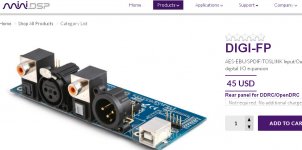
For quickly getting satisfaction from the STM32F7, you shall rely on the $45 MiniDSP MINI-FP. See the attached .jpg.
The audio must come from SPDIF or Toslink.
The USB connector is there as an island, accessible from the 5-pin header. It is there in case you want to add some USB functionality later on. Like hooking the STM32F7 on a PC, for getting it controlled/configured by a PC.
You provide a clean 48 kHz clock, coming from a 12,288 kHz quartz oscillator hardware-divided by 256.
The 48 kHz clock is your master audio clock, global.
The 12,288 kHz enters the Audio Clock Input pin of the STM32F7.
The MINI-FP delivers a clean I2S entering the STM32F7 I2S1, not SAI.
The STM32F7 does the DSP at 48 kHz.
The STM32F7 outputs four I2S issued by SAI1/A, SAI1/B, SAI2/A, SAI2/B all in I2S protocol.
You digital crossover can be stereo 4-way.
Your power amplifiers need to be TDA7801 or TDA7802.
They are all I2S-input, class B.
They don't require a MCLK.
They require a I2C control bus.
They feature a basic sensitivity control (12 dB range in 4 steps), that you must complement by down-scaling the audio data for controlling the volume. Using the lowest sensitivity (3 Vrms for full scale audio), at quiet domestic listening levels, the required audio data down-scaling remains light, say 20 dB. The dynamic will fall from 105 dB to 85 dB, still an appreciable value.
You can hook each TDA7801 or TDA7802 :
- locally, as close as possible to the STM32F7
- remotely through a 5 meter CAT5 cable and optical isolation
The CAT5 cable wiring is :
1 GND
2 +48 kHz
3 -48 kHz
4 I2S bitclock
5 I2S data
6 I2C sda
7 I2C scl
8 +48 V max 350 mA
As you can see, the 48 kHz is conveyed using a differential pair, for preserving the quality.
You can hack a FX-Audio D802 amplifier.
Take its remote control.
Take its remote control receiver (3-pin device, black, next to the volume pot) and hook it on the STM32F7.
Get the STM32F7, learning the remote control codes.
Take the FX-Audio D802 display, and hook it on the STM32F7.
Get the STM32F7, driving the display just like the FX-Audio D802 does (volume, etc).
Program the STM32F7 "bare metal", in C language, using a do ... loop for background tasks like slow housekeeping (buttons, ...).
The DSP should occur under the 48 kHz interrupt, in assembly language.
The DSP code, if only involving IIR Biquads, should read on a single A4 page.
Every 48 kHz tick, the new I2S-in-register gets read, the IIR BiQuad cells get updated, and the new resulting audio samples (eight if there are eight channels) get written into their respective SAI-out-registers.
No audio buffer !
From there, you may add bells and whistles like the volume control (doesn't need to be remote at the beginning), the remote volume control, some USB connectivity for uploading new IIR BiQuads coefficients, etc.
The less you program, the best.
You will focus on the essentials.
Make sure somebody like me can add two stereo ADCs on two I2S-in, say I2S2-in and I2S3-in, clocked by the 12,288 kHz clock and the 48 kHz clock, for grabbing four analog audio channels, and do FFT computations on them.
I will rely on this for measuring the transfer functions, in workbench mode.
This way a simple all-in-one system can be built, that's both an analyzer, a filter designer (possibly automatic when relying on FIR filters), and a crossover.
All the best,
Steph
Attachments
Last edited:
Hi,
I really, really want to keep it simple: Stm32F7 USB in to SPDIF out. This is the beauty and the interest of this nucleo platform. However, I agree that correct USB Async control flow seems to be the missing part.
I will start with the provided USB implementation.
At the moment, I'm prototyping the thing with the Stm32F4 discovery board that I have. If I succeed to implement UDB /DSP/ 2xI2S on that board, I will by the Nucleo F7 one and go to the full implementation.
Do you have one of those Nucleo stm32F7 board ? Can we had the Audio Xtal (XT3) on board ? Does it needs additional components (capacitors, resistors, ...) ? I have to set-up my BOM for the final implementation.
JMF
Therefore, I'm advising to do like tjaekel. He stopped dealing with the STM32F4 / STM32F7 USB audio issues. He bought a MiniDSP DIGI-FP, he supplied a high-quality quartz-derived 48 kHz clock to it, and that's it, from any SPDIF or Toslink audio source, the STM32F7 could immediately read audio using I2S protocol without worrying about jitter, as the DIGI-FP embeds a high-quality hardware-based ASRC nobody should worry about.I really, really want to keep it simple. However, I agree that correct USB Async control flow seems to be the missing part.
What's regarding the audio input, Async USB audio is opposite to simplicity, because even if you succeed in "simply" copy-pasting some working code, it probably will emanate from the Linux community, in the form of a "driver" asking for massive dependencies and complicated software architecture and operating system, that nobody will ever recognize as "simple". I think this is the main, obvious reason, why tjaekel stopped fiddling with Async USB audio on the STM32F4 or STM32F7.
What's regarding the multichannel audio output, your choice of relying on SPDIF goes against simplicity, and against your declared goal of achieving low jitter on a STM32 microcontroller.
SPDIF is not simplicity compared to I2S.
SPDIF (consumer grade) doesn't enable to control the power amp volume.
SPDIF obliges you to rely on SPDIF-in power amplifiers. Now, look what's inside such a SPDIF-in power amplifier, first the SPDIF to I2S converter, then the quite complicated STA326 Class-D power amp. Ask yourself if this is "simple" stuff.
The STM32F7 SAI1 A/B and SAI2 A/B exploited in I2S protocol, directly connecting to I2S-in TDA7801/7802 Class-B power amplifiers, is a simple, realistic approach, giving you the intellectual satisfaction of controlling everything from A to Z.
You may say that the WAF (Wife Acceptance factor) is not going to be high, as the I2S-out approach forces you to build a shoe-box hosting the STM32F7 and at least two TDA7801/7802 power amps, and heatsinks, not to mention the AC power supply, possibly external.
In return, the speakers remain passive. They don't require an AC outlet. That's excellent for the WAF.
The cherry on the pie is that you can rely on Speakon-4-wire connectors and cabling, in case of 2-way speakers. Those cables are easy to handle. Your wife may like them more, than the usual ugly speaker cables.
In case of 4-way speakers, you can rely on Speakon-8-wire connectors and cabling. Let me say that if your wife agrees your monstrous 4-way speakers, she certainly won't see much harm in the Speakon-8-wire connectors and cabling.
The CAT5 proposition that I made is due to remain a joke for most people.
But wait a minute. Do you know isoSPI from Linear Technology ?
There is a market for a CAT5 wire carrying a high-quality 48 kHz frame sync (one copper pair), a isoTDM-TX (one copper pair), a isoTDM-RX (1 copper pair), and a isoSPI/I2C (one copper pair), with the above copper pairs featuring PoE conveying a 48 volt DC power up to 350 mA.
A person that's able to understand the inner working of isoSPI from Linear Technology, is able to design a tiny FPGA doing such CAT5 digital audio transport, the way I have laid it out. This is a super-robust audiophile-grade digital audio interconnect, exhibiting no latency, operating in the strict respect of the master clock, and fully transparent.
The day such CAT5 digital audio transport becomes available, there will be no architectural difference between simple & high-quality centralized digital crossovers (STM32F7 and TDA7801 or TDA7802 in a shoe-box), and other systems organized like a STM32F7 operating as digital preamp, connecting to active speakers featuring a CAT5 digital audio input.
This is high-end consumer audio, and cheap, and robust. This has nothing to do with AVB (Audio-Video-Bridging) that I consider to be inappropriate for high-end consumer audio.
In case of relying on Speakon-8 instead of CAT5, the speakers can get more DC power, at the cost of equipping the Speakon-8 cables with adequate copper sections and insulations, leading to a decent DC resistance, and leading to a decent high frequency impedance and bandwidth.
The aim is to reach a 100 Mbit/s net bandwidth, thanks to the FPGA embedding some basic adaptive channel equalization (LMS or DMLS Algorithm).
Why 100 Mbit/s ? Because of 8 audio channels x 32 bits x 192 kHz = 49.152 Mbit/s.
It may be required to rely on phantom AC power for avoiding electro-migration issues. What frequency to use ? For safety reasons, the instantaneous voltage should not exceed 60 volt. Considering the Speakon-8 possibilities, the instantaneous current should not exceed 5 amp.
Such is my specification.
In case somebody able to design a tiny FPGA dares working on this with me, I'll share the experience, and the profits.
Steph
Last edited:
- Status
- This old topic is closed. If you want to reopen this topic, contact a moderator using the "Report Post" button.
- Home
- Source & Line
- Digital Line Level
- Can low jitter be achieved with STM32 microcontroller