Hi soren,
Regarding the differences between 1021 and 1121, the two boards have different approaches in clock circuitry, vref and also dac ladder, is that right?
1021 is 28 bit sign magnitude segmented 1msb magnitude, 2 bit thermometer and 25 bit r2r using 7/8x4 shift register outputs
1121 is 32 bit sign magnitude 7 msb thermometer and 25 bit r2r using 8/8x4 shift register outputs.
Is that right?
Hi Bogdan!
I saw you posted: "However, it works, but i think something is not good. With the original clock, i sniffed the i2c us between fpga and clock and i had a lot of readings, 3-4 on second. In stock configuration, the fpga, actually controls the programable clock and it is doing it frequently. I assume is something relative to the fifo states, full or empty, and the difference between clock domains."
Do you say that in stock mode, checking the i2c to the clock, you see several clock change order per second? Is that correct?
What input did you use at the time?
//
4-5 times a second on i2s using stock configuration. Didn’t checked on spdif.Hi Bogdan!
I saw you posted: "However, it works, but i think something is not good. With the original clock, i sniffed the i2c us between fpga and clock and i had a lot of readings, 3-4 on second. In stock configuration, the fpga, actually controls the programable clock and it is doing it frequently. I assume is something relative to the fifo states, full or empty, and the difference between clock domains."
Do you say that in stock mode, checking the i2c to the clock, you see several clock change order per second? Is that correct?
What input did you use at the time?
//
I think Sören claimed a time constant for the digital PLL to be 30 seconds. To me this would mean that the fastest update of the clock should be once every 30 seconds but typically slower. It of course depends on the source but what you observed sees to me be faulty behaviour or to small payload buffer.
Something is wrong. Please try with s/pdif. It has a least standardised variation - at least of you use a CD player.
I was afraid of this and it also explains why Sören don't want to implement a printout for every time the clock is changed. I wanted to know this so one can take measures in order to require the least amount of needed clock adjustments.
I wonder if one could make a very simple HW indicator with a LED, a resistor and a capacitor to form a integrating measurement indicator of the I2C activity- a 2 pole, hooked between the I2C pin and ground - this LED should ideally never be lit...
//
Took a look at the manual and see the MODE parameter is not mentioned within the UMANAGER section.
I am sure it is still available in UMANAGER, just wanted you to know.
Hi all,
Is there a plan for new firmware?
I see there are requests for new firmware but what's the TO-DO list for the new firmware?
If there's nothing to improve/fix, then there wouldn't be a new firmware I believe.
Soren, pleeeeeze come back to 1121. We want to get new update with more taps and new filters. You promised.
TNT,
Just for you I updated the dam1121 firmware to make the Vxx command more failsafe. Okay, I was actually working the the dam1121 firmware anyway to support the new dam1121-01 variation....
dam1121 firmware rev 1.09 will be posted on the soekris website soon.
13th July 2016, 05:08 PM
Time flies ;-)
//
Søren - every so often I check on soekris.dk in the fading hope I’ll find the promised firmware.
It's the hope that kills.
As this topic is very slow (I guess only few people share how they installed their dam1121) here is my contibution and hopefully inspiration for others:
I already purchased the dam1121 a few months ago but now finally got around to make a start building the P/S section and other parts.
I made the schematic just now and need to make some up-to-date pictures of how the build is progessing at this moment.
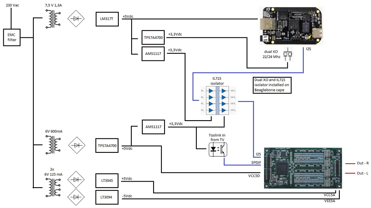
The BeagleBone Black is running with the Botic driver enabling it to send out I2S directly to any DAC.
The nice thing about Botic it can use external (better) clocks and also having separate clocks for 44.1k and 48k.
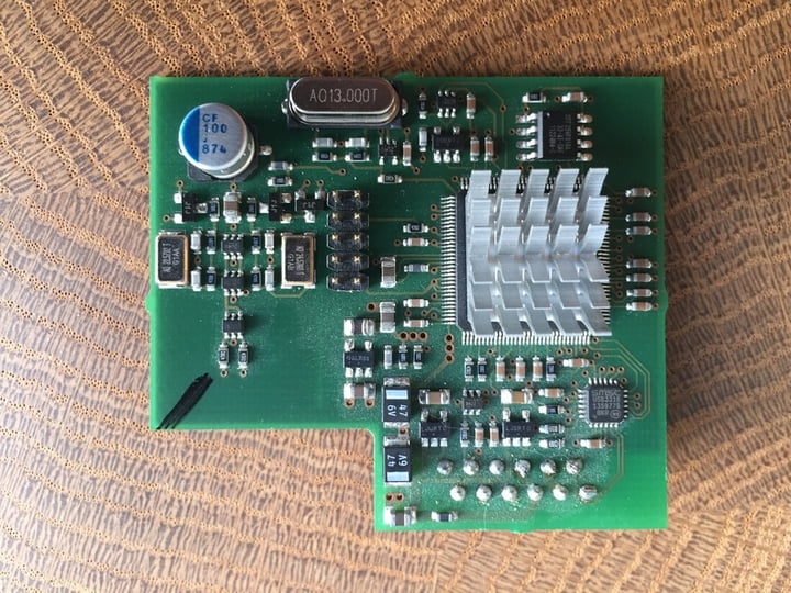
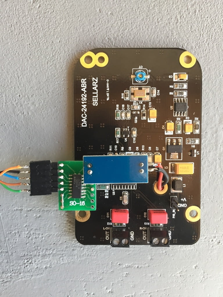
My current system uses an ES9023 DAC board from Sellarz.
The P/S is made of LM317T regulators for the DAC and BBB and have only a 22.5792 clock as external and use the onboard 24.576 clock when I play a 48/96/192 file (which are very few in my music library)
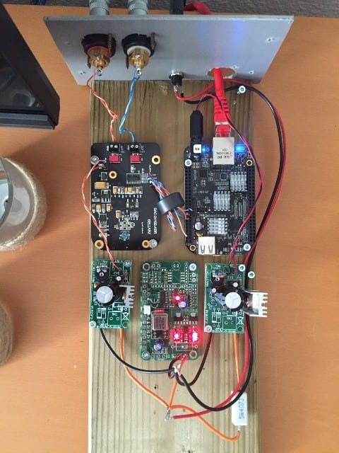
This is how it looks like now:
Testing before final assembly:
After final assembly:
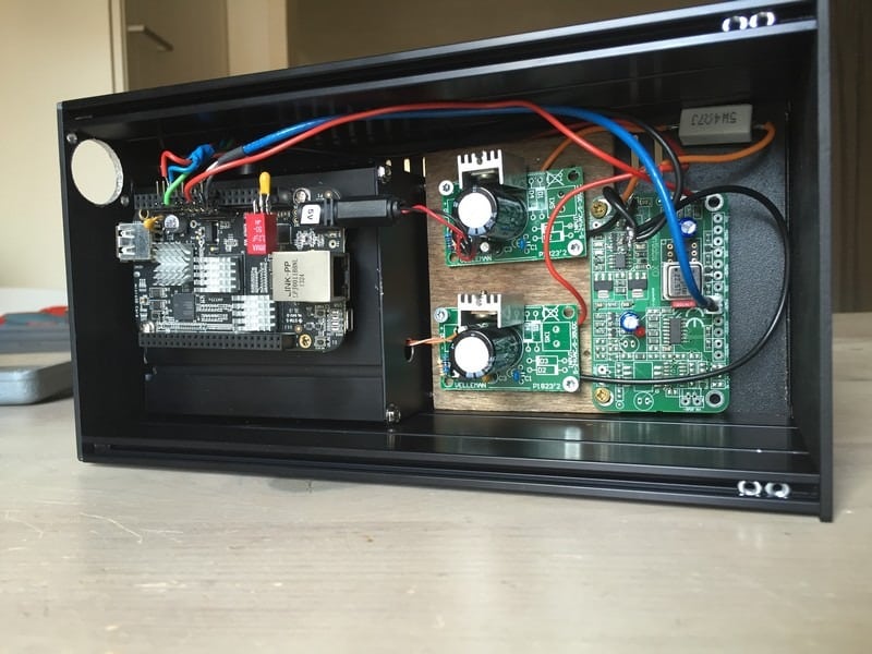
The Sellarz DAC is in the added enclosure ( vault ?? ) to minimise EMC effects.
I could buy an identical second-hand DAC board for little money so always easy to have a spare or for experimenting.
Having also a second BBB at hand I decided to build a better system with a hacked XMOS board from a previous DAC which has a double clock circuit.
I managed to find the traces which I needed to power and control the circuit and made a daughter board for the BBB and installed a digital isolator at the DAC board.
XMOS - USB receiver board:
Hacked:
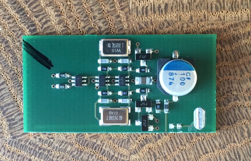
Installed:
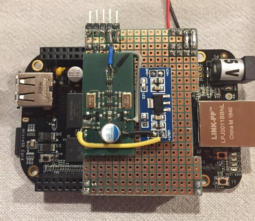
Digital received installed at I2S input.
Unfortunate I never got to finalise it to get it installed in the enclosure but had it working.
The main reason not to finish that project was I got triggered by the R2R DAC's and finally ordered the dam1121.
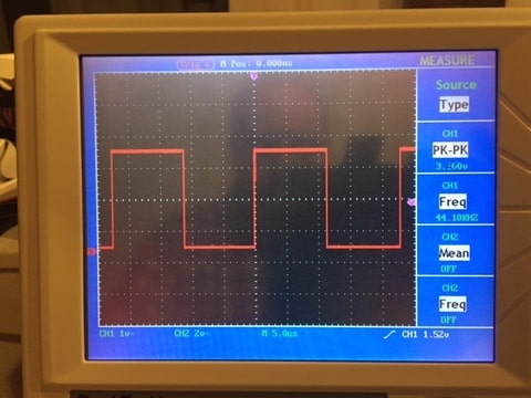
With the test setup I even made some measurements of the I2S signal before and after the digital isolator and it was very clear that the isolator removed lot's of noise sending out a cleaner signal compared to the input.
44.1 LRCLK in:
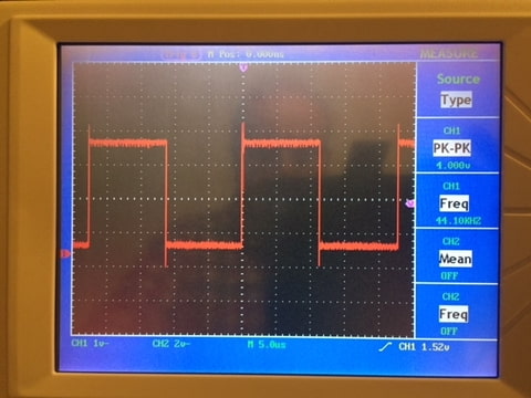
44.1 LRCLK out:
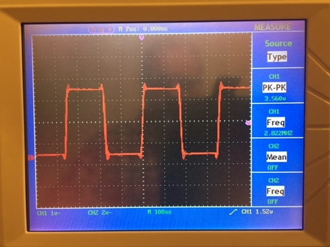
44.1 BCK in:
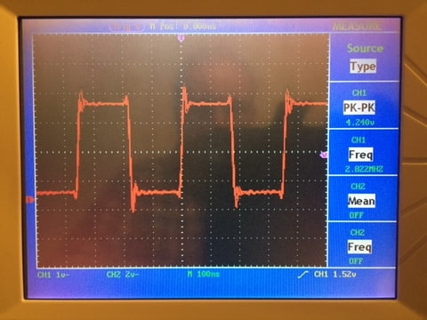
44.1 BCK out:
I will make some pictures of the dam1121 build and put them here too but according to the schematic above you now know what to expect
I already purchased the dam1121 a few months ago but now finally got around to make a start building the P/S section and other parts.
I made the schematic just now and need to make some up-to-date pictures of how the build is progessing at this moment.
The BeagleBone Black is running with the Botic driver enabling it to send out I2S directly to any DAC.
The nice thing about Botic it can use external (better) clocks and also having separate clocks for 44.1k and 48k.
My current system uses an ES9023 DAC board from Sellarz.
The P/S is made of LM317T regulators for the DAC and BBB and have only a 22.5792 clock as external and use the onboard 24.576 clock when I play a 48/96/192 file (which are very few in my music library)
This is how it looks like now:
Testing before final assembly:
After final assembly:
The Sellarz DAC is in the added enclosure ( vault ??
) to minimise EMC effects.I could buy an identical second-hand DAC board for little money so always easy to have a spare or for experimenting.
Having also a second BBB at hand I decided to build a better system with a hacked XMOS board from a previous DAC which has a double clock circuit.
I managed to find the traces which I needed to power and control the circuit and made a daughter board for the BBB and installed a digital isolator at the DAC board.
XMOS - USB receiver board:
Hacked:
Installed:
Digital received installed at I2S input.
Unfortunate I never got to finalise it to get it installed in the enclosure but had it working
.The main reason not to finish that project was I got triggered by the R2R DAC's and finally ordered the dam1121.
With the test setup I even made some measurements of the I2S signal before and after the digital isolator and it was very clear that the isolator removed lot's of noise sending out a cleaner signal compared to the input.
44.1 LRCLK in:
44.1 LRCLK out:
44.1 BCK in:
44.1 BCK out:
I will make some pictures of the dam1121 build and put them here too but according to the schematic above you now know what to expect
As this topic is very slow (I guess only few people share how they installed their dam1121) here is my contibution and hopefully inspiration for others:
I already purchased the dam1121 a few months ago but now finally got around to make a start building the P/S section and other parts.
I made the schematic just now and need to make some up-to-date pictures of how the build is progessing at this moment.
The BeagleBone Black is running with the Botic driver enabling it to send out I2S directly to any DAC.
The nice thing about Botic it can use external (better) clocks and also having separate clocks for 44.1k and 48k.
My current system uses an ES9023 DAC board from Sellarz.
The P/S is made of LM317T regulators for the DAC and BBB and have only a 22.5792 clock as external and use the onboard 24.576 clock when I play a 48/96/192 file (which are very few in my music library)
This is how it looks like now:
Testing before final assembly:
After final assembly:
The Sellarz DAC is in the added enclosure ( vault ??
I could buy an identical second-hand DAC board for little money so always easy to have a spare or for experimenting.
Having also a second BBB at hand I decided to build a better system with a hacked XMOS board from a previous DAC which has a double clock circuit.
I managed to find the traces which I needed to power and control the circuit and made a daughter board for the BBB and installed a digital isolator at the DAC board.
XMOS - USB receiver board:
Hacked:
Installed:
Digital received installed at I2S input.
Unfortunate I never got to finalise it to get it installed in the enclosure but had it working
The main reason not to finish that project was I got triggered by the R2R DAC's and finally ordered the dam1121.
With the test setup I even made some measurements of the I2S signal before and after the digital isolator and it was very clear that the isolator removed lot's of noise sending out a cleaner signal compared to the input.
44.1 LRCLK in:
44.1 LRCLK out:
44.1 BCK in:
44.1 BCK out:
I will make some pictures of the dam1121 build and put them here too but according to the schematic above you now know what to expect
Looks great.
I bought the dam1121 in Apr this year. However, I still can't make it work. I look forward to your update.
As this topic is very slow (I guess only few people share how they installed their dam1121) here is my contibution and hopefully inspiration for others:
Interesting development. You might consider the BBB isolator/reclocker board that DIYaudio member ppy developed on the Signalyst DSC thread, here's my one;
https://www.diyaudio.com/forums/digital-line-level/254935-signalyst-dsc1-153.html#post5894378
It think it will do the same thing as your project but on a single small board that sits on top of the BBB. The only downside is the need to solder small smd parts.
I already have the IL715 isolator chip installed.
If I am informed correct the dam1121 does re-clocking so I think I already have both covered this way ( isolation and re-clocking ).
Your board looks nice and if discovered last year I might get tempted
Yes, the board I'm suggesting doesn't offer you new functionality, just suggesting it as a small, neat, integrated solution...
I hacked some kit I had available and put it together to fullfill the needs I had.
This is a one-time solution and unlikely for anybody to copy.
The PPY can be replicated many times so it is a decent solution and like I said .. if I knew about this board last year I might have bought it
This is a one-time solution and unlikely for anybody to copy.
The PPY can be replicated many times so it is a decent solution and like I said .. if I knew about this board last year I might have bought it
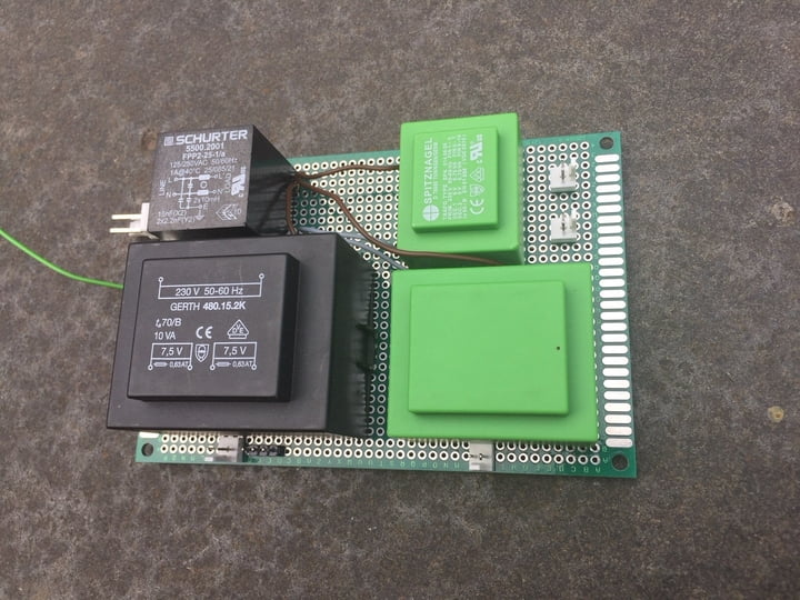
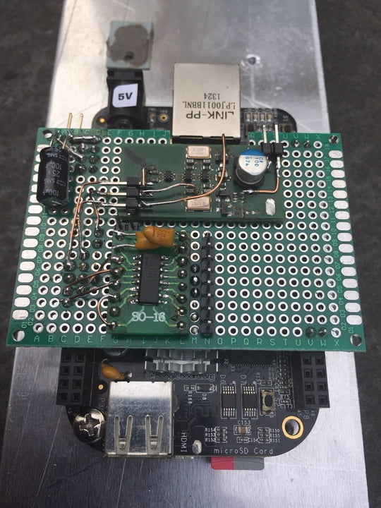
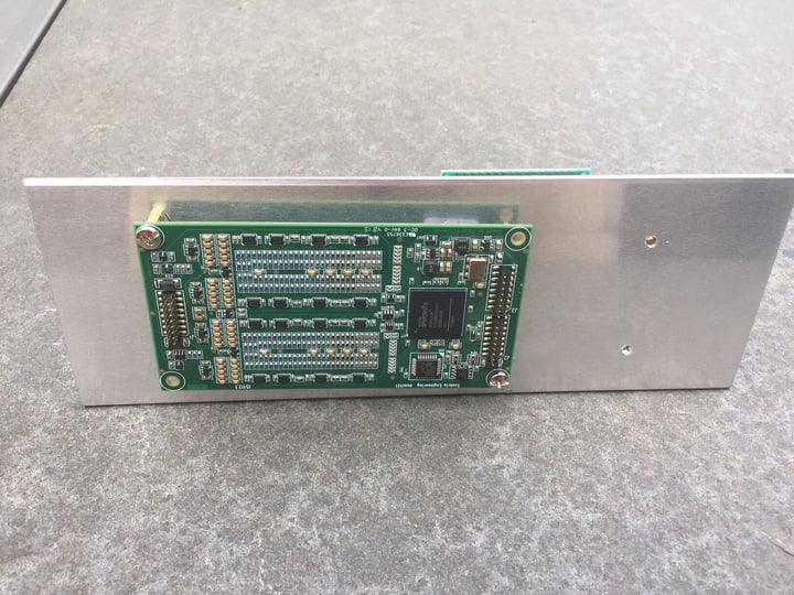
Here is the update on the Dam1121 buildup.
AC board:
Beaglebone with updated XO board and digital isolator:
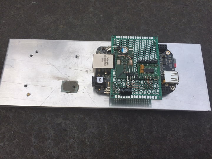
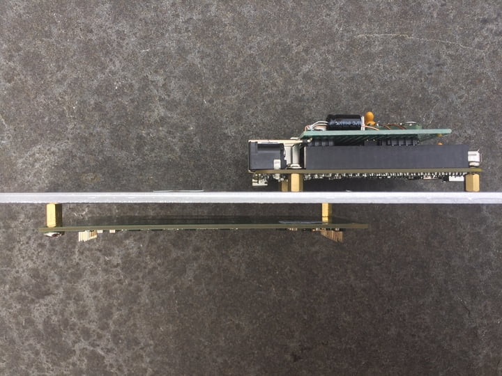
The aliminium plate is cut to fit exactly in vertical position in the black enclosure which I use now for the old setup.
The power supplies needs to be fabricated / installed.
The low noise regulators like TPS7A47xx and LT30xx are nice compact 3-pin boards from LDOVR which are in order now.
For the soekris board I also have adapter pcb’s from 2.0 to 2.54 spacing for easy connections.
AC board:
Beaglebone with updated XO board and digital isolator:
The aliminium plate is cut to fit exactly in vertical position in the black enclosure which I use now for the old setup.
The power supplies needs to be fabricated / installed.
The low noise regulators like TPS7A47xx and LT30xx are nice compact 3-pin boards from LDOVR which are in order now.
For the soekris board I also have adapter pcb’s from 2.0 to 2.54 spacing for easy connections.
- Home
- Source & Line
- Digital Line Level
- Building with the Soekris dam1121