Sure, but the question was also if any of you experience the same, and how to overcome this using the internal DACs and output opamps.
Of course one could end up with so many additional components that just using a DAC which has already taken care of this is a better option.
But would like to hear some experiences. Thanks.
There is a 1.5V DC offset on the output of the ada1701, a blocking capacitor is used but you still have a change in voltage on the output as it charges and discharges causing it to pop on the outputs. You could deal with it by adding a mute circuit to connect / disconnect the output before the adau1701 powers on/off.
Member
Joined 2018
FreeDSP SMD A/B Schematic
Hello Baldin & SubSonicks-San,
Here is an example adding power on/off mute on ADAU1701.
DIY DSP PROCESSOR PROJECT PAGE
(Solid-state mute requires negative voltage when releasing mute.)
There is a 1.5V DC offset on the output of the ada1701, a blocking capacitor is used but you still have a change in voltage on the output as it charges and discharges causing it to pop on the outputs. You could deal with it by adding a mute circuit to connect / disconnect the output before the adau1701 powers on/off.
Hello Baldin & SubSonicks-San,
Here is an example adding power on/off mute on ADAU1701.
DIY DSP PROCESSOR PROJECT PAGE
(Solid-state mute requires negative voltage when releasing mute.)
Last edited:
Mute
Very interesting CyberPit
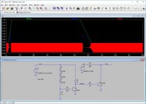
Thinking if it can be done even more simple ... sensing Vcc with a Zenner (here 3 diodes), and using this to mute the output at start up and close down
Have not tried in reality yet ... but it seems to work in sim ...
Any thoughts
Very interesting CyberPit
Thinking if it can be done even more simple ... sensing Vcc with a Zenner (here 3 diodes), and using this to mute the output at start up and close down
Have not tried in reality yet ... but it seems to work in sim ...
Any thoughts
Attachments
Member
Joined 2018
Baldin-San, I also like to design as simple as possible.
There are few things to remind the constraints for real-world simulation.
- DAC output waveform voltage may exceeds 0.6Vpeak from the GND level. We should prevent form the waveform peak clipping.
- Need a negative voltage power supply for perfect releasing of mute-Tr driving function.
- Need a reserved positive power supply after power-down. (To Keep muting after the power down)
Last edited:
Hey everybody! I have the exactly same problem with freeDSP SMD B:
Output 2/3 are lousy noisy! Maybe it is a layout mistake? In my opinion, the whole board is not designed really professional...
I will try a linear regulator instead of the switching regulator. Any more ideas?
Output 2/3 are lousy noisy! Maybe it is a layout mistake? In my opinion, the whole board is not designed really professional...
I will try a linear regulator instead of the switching regulator. Any more ideas?
For all who have noise problems with freeDSP SMD:
The layout is a big FAIL!
seems like someone did his first try in layouting...
Dear future PCB designer:
First of all make a proper grounding concept. A circuit like this should have a groundplane. DON'T cut the groundplane through and through with any kinds of signals!
If your layout program produces small copper islands, please leave them out instead of connecting useless 10 square millimetre islands with one via.
Don't mix analog and digital signals close together. At least, take care for some ground shielding between them! Keep analog signals away from everything - especially digital signals! And yes, a charge pump running on few hundreds kHz is noisy too! If you decide to use a charge pump, don't place it close to the output filters. And again: use a lot of GND. And vias are not so expensive anymore, use more of them, they will be your friends")
To solve the noise problem:
cut the signal lanes from DSP outputs 2/3 close to the DSP. Take a piece of thin shielded wire and connect the outputs straight to the output filters (the two 2k Resistors).
I will do more modifications, mainly fixing some GND rubbish.
The layout is a big FAIL!
seems like someone did his first try in layouting...
Dear future PCB designer:
First of all make a proper grounding concept. A circuit like this should have a groundplane. DON'T cut the groundplane through and through with any kinds of signals!
If your layout program produces small copper islands, please leave them out instead of connecting useless 10 square millimetre islands with one via.
Don't mix analog and digital signals close together. At least, take care for some ground shielding between them! Keep analog signals away from everything - especially digital signals! And yes, a charge pump running on few hundreds kHz is noisy too! If you decide to use a charge pump, don't place it close to the output filters. And again: use a lot of GND. And vias are not so expensive anymore, use more of them, they will be your friends
To solve the noise problem:
cut the signal lanes from DSP outputs 2/3 close to the DSP. Take a piece of thin shielded wire and connect the outputs straight to the output filters (the two 2k Resistors).
I will do more modifications, mainly fixing some GND rubbish.
Member
Joined 2018
A Polite Notice
I will add an comment above objection
dymoneum-San points out "FreeDSP SMD B", not for FreeDSP (Classic) SMD A/B
Those are completely different design. SMD A/B don't have those kind of noise issue with 2V RMS outputs.
freeDSP | An Open-Source Low-Budget Audio DSP
For all who have noise problems with freeDSP SMD:
The layout is a big FAIL!
seems like someone did his first try in layouting...
I will add an comment above objection
dymoneum-San points out "FreeDSP SMD B", not for FreeDSP (Classic) SMD A/B
Those are completely different design. SMD A/B don't have those kind of noise issue with 2V RMS outputs.
freeDSP | An Open-Source Low-Budget Audio DSP
Member
Joined 2018
FreeDSP Classic SMD A/B plus-II
Hello to all
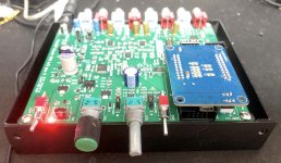
An extended 2in 6out FreeDSP SMD A/B, which called FreeDSP Classic SMD A/B plus-II design had released.
Plus features are ..
Git-Hub: GitHub - CyberPit/FreeDSP_Classic_SMD_AB_plus-II: An extended version of FreeDSP Classic SMD A/B
Forum:FreeDSP Classic SMD A/B plus II is on Development
CyberPit
Hello to all
An extended 2in 6out FreeDSP SMD A/B, which called FreeDSP Classic SMD A/B plus-II design had released.
Plus features are ..
- Additional PCM5102A DAC for DIG6/7 output.
- Integrated FreeUSBi slot.
Git-Hub: GitHub - CyberPit/FreeDSP_Classic_SMD_AB_plus-II: An extended version of FreeDSP Classic SMD A/B
Forum:FreeDSP Classic SMD A/B plus II is on Development
CyberPit
Attachments
hello,
I visited your homepage recently and I like your Open Hardware approach.
At the moment I try to design a new kind of e-guitar in freecad (also Open Hardware). There will be a automatic tuning function included. This is similar to tronical tuners (Welcome - TronicalTune - Tronical - autotunes your guitar in seconds) but it should on the other side of strings because this will be a headless guitar. So piezo cristalls under each string takes the signal to a DSP, which should do:
filtering / amplify signals / analyze frequency
and operate a motor control unit which supply my 6 motors so the strings getting loose or tighter.
Additionally all string-signals should be transfered via USB.
So I looked at Aurora but it is too big. A square shape is not ideal for my project. Infinitas looks promising but I did not find any dimensions.
It will still take a year for me to finish my project. I learned a lot since I started it. Next thing is to get an overview what electronic/engines/DSP I need for this functions.
Do you think that I will need a separate amplification stage for the piezo crystals or will the FreeDSP amplification enough?
(Sorry for the noob question)
Is there a new product on the horizon? BT 5.2 will be very interesting for low latency audio applications.
kind regards, from Austria Dominik
Member
Joined 2018
Filtering for guitar Tuning
Hi amplify1-San,
Regards,
CyberPit
Hi amplify1-San,
Almost 35 years ago, I had tear-down a product which named "IVL Pitch Rider" as a Guitar to MIDI interface. It uses separate magnetic pick-up into six BPFs. (On each string) Then the signals convert to square-wave to detect the pitch. Pitch and Picking detection was performed by a few 8051 MCUs. Detected pitch and velocity ware convert to MIDI data. The BPF filter was 2pole (I'm not sure). So I think ADAU1701 has enough DSP performance for the six 8pole(48dB/oct) BPF processing and level compressions. But I guess the pitch detection will be a difficult in the same core.(Just my impression) So my recommendation is using Op-Amps for adjusting leve, then Cirrus Logic CS5368 in TDM fromat (8ch inputs: 6 for Each string 1 for Normal Sound and 1 for AUX) feeds to FreeDSP Classic SMD A/B plus II. Separate filtered output will be almost the Sin wave, so may be it's easy to detect the pitch such as Reciprocal-Counter, kind of PLL devices or Phase Comparator to the reference pitch signal.At the moment I try to design a new kind of e-guitar in freecad (also Open Hardware). There will be a automatic tuning function included. This is similar to tronical tuners (Welcome - TronicalTune - Tronical - autotunes your guitar in seconds) but it should on the other side of strings because this will be a headless guitar. So piezo cristalls under each string takes the signal to a DSP, which should do:
filtering / amplify signals / analyze frequency
and operate a motor control unit which supply my 6 motors so the strings getting loose or tighter.
Do you think that I will need a separate amplification stage for the piezo crystals or will the FreeDSP amplification enough?
I guess sending a sound in SBC format will not be a good idea for the pitch detection. Motor driving control data via UART communication will fit for your case. In that case, latency will not be a big matter.Is there a new product on the horizon? BT 5.2 will be very interesting for low latency audio applications.
Regards,
CyberPit
Last edited:
Is there any way to get, preferably, SPDIF in and maybe out using the pins available on the FreeDSP Classic Through hole version? If not, can I get I²S in and out?
I'd also like to have a rotary encoder for adjusting volume as it's for a pair of 15" in dipole. Matching levels to my speakers would be a lot easier with a volume knob.
I've got two working boards. If this isn't an option, I'll have to look at another solution using ADAU1452/ADAU1466.
I'd also like to have a rotary encoder for adjusting volume as it's for a pair of 15" in dipole. Matching levels to my speakers would be a lot easier with a volume knob.
I've got two working boards. If this isn't an option, I'll have to look at another solution using ADAU1452/ADAU1466.
Member
Joined 2018
2.1ch:Hi there
Is there any documentation or tutorial on using Classic free dsp in 2.1 mode and how to use this board for room correction.
Maybe something looks like you wants to do ...
Google Translate
(Bottom of the page, Machine translation)
room correction:
ADAU1701 is not so powerful, so the convolution type correction is difficult. Some MLSSA type EQ response correction will be a compromised solution.
Google Translate (Using Simulation Elements, Machine translation)
Member
Joined 2018
ADAU1451 or ADAU1466 will be better for the point of view of cost-performance. Those are 6 times faster than ADAU1701. And much more memory space for the data processing.What would you suggest for Eq response correction which would be better than ADAU1701.
I found several kinds of ADAU1466 boards are selling...
ADAU1466 - Buy ADAU1466 with free shipping on AliExpress
Member
Joined 2018
FreeDSP ADAT-IO-x4 Released
Hello FreeDSP freaks,
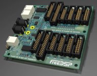
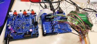
Yesterday, I released ADAT-IO-x4 at my web pages.
[GitHub repository]
GitHub - CyberPit/freeDSPx-ADAT-IO-x4c
[Machine Translation]
Google Translate
[Original Japanese Page]
DIY DSP PROCESSOR PROJECT PAGE
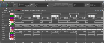
It can transfer 44.1kHz/48kHz I8S(4times I2S data, BCLK and LRCK) encode into single TOS-LINK optical cable. (TX Board)
RX board receive an ADAT optical stream and decoded to I8S outputs. You can connect Free DSP board and 8channel(4 Stereos) DACs with one optical cable. It will be useful for building multi-way powered-speaker system or wall installations...
CyberPit
Hello FreeDSP freaks,
Yesterday, I released ADAT-IO-x4 at my web pages.
[GitHub repository]
GitHub - CyberPit/freeDSPx-ADAT-IO-x4c
[Machine Translation]
Google Translate
[Original Japanese Page]
DIY DSP PROCESSOR PROJECT PAGE
It can transfer 44.1kHz/48kHz I8S(4times I2S data, BCLK and LRCK) encode into single TOS-LINK optical cable. (TX Board)
RX board receive an ADAT optical stream and decoded to I8S outputs. You can connect Free DSP board and 8channel(4 Stereos) DACs with one optical cable. It will be useful for building multi-way powered-speaker system or wall installations...
CyberPit
Attachments
- Home
- Source & Line
- Digital Line Level
- freeDSP main thread