Hello Friends,
On the FreeDSP Guidelines Wiki there is a call to have a distribution circuit for the Master Clocks. Here is what is written.
I'm designing a board that will use the FreeDSP Expansion Connector to connect a DSP Main Board, to ADC/DAC Add-on Boards. I'm wondering if there is any more information out there regarding clock distribution, or I2S distribution in general. Upon review of the various FreeDSP boards, the clock distribution, or I2S distribution is done differently. I document my search here on the DiyAudio Thread "Clock Repeater IC, Jitter correction ic, clock distibution". Some circuits are using Gate Buffers for all of the I2S lines... Other circuits are using just a clock buffer.
Options seem to include
- Fan-out IC for Master Clock
- Buffer of all I2S lines
My question for the FreeDSP users is surrounding real world experience. Do any of these circuits provide a more reliable outcome than others? What users are connecting add-on boards using long lines? Are any users out there connecting multiple add-on boards on an unbuffered signal? Buffered signal? Fan-out for MCLK only? What's the outcome? I can tell you that in my breadboard tests I'm finding that if I connect more than one board to my breadboard using 6 inch cables I get problems. I'm wondering if maybe we could come up with a more concrete recommendation and add it to the wiki, something that we can all agree will send I2S a distance. Maybe 6 inches to each board? Maybe 12 inches? 18 inches? Any IC's that incorporate I2S buffering specifically into the datasheet? Something designed to strengthen the I2S lines... That would be really nice wouldn't it be!?
On the FreeDSP Guidelines Wiki there is a call to have a distribution circuit for the Master Clocks. Here is what is written.
MCLK distribution
All main-boards and slave boards need to be synchronous to a common master clock (MCLK). Therefore future freeDSP main-boards must feature a MCLK distribution circuit, which provides several synchronous but independant MCLK outputs. These will supply a MCLK to the onboard DSP and also to each expansion board via the standard freeDSP expansion connector.
freeDSP main-boards provide MCLK: 24.576 MHz
freeDSPx expansions receive MCLK via standard freeDSP expansion connector
I'm designing a board that will use the FreeDSP Expansion Connector to connect a DSP Main Board, to ADC/DAC Add-on Boards. I'm wondering if there is any more information out there regarding clock distribution, or I2S distribution in general. Upon review of the various FreeDSP boards, the clock distribution, or I2S distribution is done differently. I document my search here on the DiyAudio Thread "Clock Repeater IC, Jitter correction ic, clock distibution". Some circuits are using Gate Buffers for all of the I2S lines... Other circuits are using just a clock buffer.
Options seem to include
- Fan-out IC for Master Clock
- Buffer of all I2S lines
My question for the FreeDSP users is surrounding real world experience. Do any of these circuits provide a more reliable outcome than others? What users are connecting add-on boards using long lines? Are any users out there connecting multiple add-on boards on an unbuffered signal? Buffered signal? Fan-out for MCLK only? What's the outcome? I can tell you that in my breadboard tests I'm finding that if I connect more than one board to my breadboard using 6 inch cables I get problems. I'm wondering if maybe we could come up with a more concrete recommendation and add it to the wiki, something that we can all agree will send I2S a distance. Maybe 6 inches to each board? Maybe 12 inches? 18 inches? Any IC's that incorporate I2S buffering specifically into the datasheet? Something designed to strengthen the I2S lines... That would be really nice wouldn't it be!?
DAC 2&3 noise
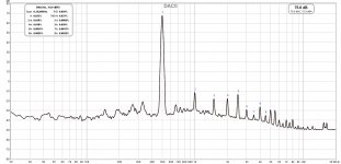
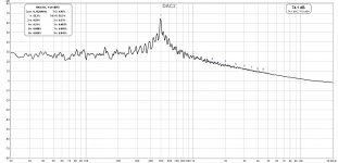
Hello, I have exactly the same problem. DAC0 and DAC1 work fine, but DAC2 and DAC3 are extremly noisy. Its a white noise and it is not from ADC (as DAC0&1 work fine). Tried 4 different power supply, USB from PC, 9V power brick, 5V from power bank and 15V PS with 7815 stabilizer. All work more or less the same, there are only subtle differences between them.
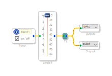
I made a project in sigma studio to generate 500Hz tone, that I fed to my ESI Juli@ sound card and analyzed it with REW, results bellow.
Hey guys,
I've just recently bought a freedsp smd B board and it's got a distinct noise on oupt 3 and 4.... prety much like pink noise... it' doesn't go away when I use a mut button before the DAC...
Hello, I have exactly the same problem. DAC0 and DAC1 work fine, but DAC2 and DAC3 are extremly noisy. Its a white noise and it is not from ADC (as DAC0&1 work fine). Tried 4 different power supply, USB from PC, 9V power brick, 5V from power bank and 15V PS with 7815 stabilizer. All work more or less the same, there are only subtle differences between them.
I made a project in sigma studio to generate 500Hz tone, that I fed to my ESI Juli@ sound card and analyzed it with REW, results bellow.
Attachments
DAC 2&3 very noisy
Hi,
Same problem for me… DAC0 & DAC1 are very clean output, but DAC2&3 are very very noisy. I don't know why. I tried different configurations in Sigma Studio, different power supply, I checked all the soldering.
Did anyone else encountered the same problem ? How can we solve it ?
Thank you very much
Hello, I have exactly the same problem. DAC0 and DAC1 work fine, but DAC2 and DAC3 are extremly noisy. Its a white noise and it is not from ADC (as DAC0&1 work fine). Tried 4 different power supply, USB from PC, 9V power brick, 5V from power bank and 15V PS with 7815 stabilizer. All work more or less the same, there are only subtle differences between them.
I made a project in sigma studio to generate 500Hz tone, that I fed to my ESI Juli@ sound card and analyzed it with REW, results bellow.
Hi,
Same problem for me… DAC0 & DAC1 are very clean output, but DAC2&3 are very very noisy. I don't know why. I tried different configurations in Sigma Studio, different power supply, I checked all the soldering.
Did anyone else encountered the same problem ? How can we solve it ?
Thank you very much
Member
Joined 2018
PCB Layout?
I don't have FreeDSP classic SMD B board. My design FreeDSP SMD A/B board don't have this kind of issue, so I can say ADAU1701 chip has four very clean audio outputs.
So I checked with SMD B ki-CAD file on Git-Hub. It seems no potential problem in schematic design. But I can see the very very long VOUT2 & VOUT3 tracks along the MCLK lines.
What will happen? if you remove the R44, R45, R46, R47, and/or additionally bypassing U7 clock driver.
Hi,
Same problem for me… DAC0 & DAC1 are very clean output, but DAC2&3 are very very noisy. I don't know why. I tried different configurations in Sigma Studio, different power supply, I checked all the soldering.
Did anyone else encountered the same problem ? How can we solve it ?
Thank you very much
I don't have FreeDSP classic SMD B board. My design FreeDSP SMD A/B board don't have this kind of issue, so I can say ADAU1701 chip has four very clean audio outputs.
So I checked with SMD B ki-CAD file on Git-Hub. It seems no potential problem in schematic design. But I can see the very very long VOUT2 & VOUT3 tracks along the MCLK lines.
What will happen? if you remove the R44, R45, R46, R47, and/or additionally bypassing U7 clock driver.
Are you suggesting its a design flaw?
I don't have hot air station yet, so desoldering or making changes is a problem. Also I purchased the board with all SMD components assembled, so I'd leave it as it is, for warranty (if there is any)
Member
Joined 2018
Are you suggesting its a design flaw?
I don't have hot air station yet, so desoldering or making changes is a problem. Also I purchased the board with all SMD components assembled, so I'd leave it as it is, for warranty (if there is any)
Hello DarkOne-San,
Well yes!
You can do as you like. Because it's a "DIY"
")
One of technique to remove SMD resistor which using with two solder irons. (Photo attached)
BTW, I have ordered this hot air tool in last week.
BGA Rework Solder Station 8858 Portable Hot Air Gun Blower 220V EU Plug Hand held Heat Gun With Welding Soldering Repair Tools-in Soldering Stations from Tools on Aliexpress.com | Alibaba Group
Attachments
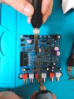
I have more than enough of DIY as you can see on attached inage.Hello DarkOne-San,
Well yes!
You can do as you like. Because it's a "DIY"
One of technique to remove SMD resistor which using with two solder irons. (Photo attached)
BTW, I have ordered this hot air tool in last week.
BGA Rework Solder Station 8858 Portable Hot Air Gun Blower 220V EU Plug Hand held Heat Gun With Welding Soldering Repair Tools-in Soldering Stations from Tools on Aliexpress.com | Alibaba Group
Weird things happened, without any change, all chanels work flawlessly now, noise is gone. I'm not sure if there is something in the grid, or some badly bahaving device in the house that cause interference.
I will test all chanels over and over again in the upcoming week

Member
Joined 2018
Capacitive Loads?
Hello DarkOne-San,
A possibility of MCLK interference is gone.
I guess some oscillation possibility depends on output loads.
Voltage follower's negative input phase can be shift to -180 degrees over 1MHz if the voltage follower's output impedance raise to 30ohms around.
Hope you can succeed to shut the evils...
Regards,
CyberPit
I have more than enough of DIY as you can see on attached inage.
Weird things happened, without any change, all chanels work flawlessly now, noise is gone. I'm not sure if there is something in the grid, or some badly bahaving device in the house that cause interference.
I will test all chanels over and over again in the upcoming week View attachment 768991
Hello DarkOne-San,
A possibility of MCLK interference is gone.
I guess some oscillation possibility depends on output loads.
Voltage follower's negative input phase can be shift to -180 degrees over 1MHz if the voltage follower's output impedance raise to 30ohms around.
Hope you can succeed to shut the evils...
Regards,
CyberPit
Hello,
DarkOne, I'm glad that the noise is gone on your FreeDSP !
Unfortunately, on mine, I still have a lot of noise on DAC 2&3. I checked once again all soldering, I changed the power supply, but nothing worked…
I'm a little bit confused and I don't know what to do.
If anyone have an idea.
Maybe I'm gonna send back this board and buy a MiniDPS…
Weird things happened, without any change, all chanels work flawlessly now, noise is gone. I'm not sure if there is something in the grid, or some badly bahaving device in the house that cause interference.
View attachment 768991
DarkOne, I'm glad that the noise is gone on your FreeDSP !
Unfortunately, on mine, I still have a lot of noise on DAC 2&3. I checked once again all soldering, I changed the power supply, but nothing worked…
I'm a little bit confused and I don't know what to do.
If anyone have an idea.
Maybe I'm gonna send back this board and buy a MiniDPS…
Working Sigma Stuio Project
Hi every one !
I'm currently trying all sorts of combinations to avoid the noise on my freedsp.
In order to eliminate a software problem, could anyone send me his fully working Sigma Studio project, tested on a freeDSP SMD-B ?
Maybe my Sigma Studio configuration is wrong…
Thank you very much !
Hi every one !
I'm currently trying all sorts of combinations to avoid the noise on my freedsp.
In order to eliminate a software problem, could anyone send me his fully working Sigma Studio project, tested on a freeDSP SMD-B ?
Maybe my Sigma Studio configuration is wrong…
Thank you very much !
Hello,
DarkOne, I'm glad that the noise is gone on your FreeDSP !
Unfortunately, on mine, I still have a lot of noise on DAC 2&3. I checked once again all soldering, I changed the power supply, but nothing worked…
I'm a little bit confused and I don't know what to do.
If anyone have an idea.
Maybe I'm gonna send back this board and buy a MiniDPS…
Hi Theol, unfortunately DAC2&3 are still noisy. Measurements are much better than what I posted earlier, it was probably some SW glitch in my measurement rig.
Anyway, DAC2&3 have 15-20dB more noise than the other channels, I posted. When I connect 93dB/2.83V tweeter to amplifier output I hear very low noise from DAC0&1 and loud noise from DAC2&3, so loud that I can hear it loudly 3 meters away.
Connecting external ADC to freeDSP board
Hi,
did you get a response or even better a solution to this question?
I have the same problem, would like to connect an external ADC via I2S but seems like the BCLK and LRCLK input signals are not connected on the board. And the ADAU1701 datasheet clearly says that these two must be externally connected to the I2S master mode output signals (MP10 and MP11).
Frank
Hey,
I have a question.
I've just got mine copy of freedsp-smd-b board from evenelements.
Could you tell me how to connect i2s signal when MP4/MP5 pins are physically not used in the board?
Sigma studio uses those pins for LRCLK/BCLK_IN.
Thanks.
Member
Joined 2018
Set in Hardware Configuration(Top) Tab and...
Hi Guys,
You can configure MPx pins in Hardware Configuration(Topside tab)
then IC1 - 170x¥140x Register Control(Bottom-side Tab)
Simile as my board configuration
DIY DSP PROCESSOR PROJECT PAGE
Cyberpit
Hi,
did you get a response or even better a solution to this question?
I have the same problem, would like to connect an external ADC via I2S but seems like the BCLK and LRCLK input signals are not connected on the board. And the ADAU1701 datasheet clearly says that these two must be externally connected to the I2S master mode output signals (MP10 and MP11).
Frank
Hi Guys,
You can configure MPx pins in Hardware Configuration(Topside tab)
then IC1 - 170x¥140x Register Control(Bottom-side Tab)
Simile as my board configuration
DIY DSP PROCESSOR PROJECT PAGE
Cyberpit
Attachments
MP4/MP5 not connected on board
Thanks for the response, but
the problem is that on my freeDSP board (Rev 1.0) the pins MP4 and MP5 are not connected at all. I just saw that there is a new release of the board (Rev 1.1) now available where these pins are connected to new pin headers.
(see also the add-on in the documentation pasted below)
In my case I will need to patch these signals by soldering cabled directly to the IC pins.
Revision 2019 - Information and changes - I²S-Issue
2019 we discovered a essential Problem with the digital audio communication on the SMD-B Board. There were two MultiPurpose-Pins unused (MP4/5), but they’re very important when it comes to getting digital audio on the Board. It turned out that the freeDSP Standard Connector can’t easily send and receive on same hardware/channel. The ADAU1701 requires a BCLK-In and a LRCLK-In for all input channel. These Inputs are MP4/5.
Changes
There was nothing changed in terms of general hardware or layout. That means besides this page the board and the Getting Started is still the same. Please note that the minimal distance to the side is slightly smaller than recommended in the design guidelines.
Additions
MP4 (INPUT_LRCLK) - is now connected to the outside world.
MP5 (INPUT_BCLK) - is now connected to the outside world.
Hi Guys,
You can configure MPx pins in Hardware Configuration(Topside tab)
then IC1 - 170x¥140x Register Control(Bottom-side Tab)
Simile as my board configuration
DIY DSP PROCESSOR PROJECT PAGE
Cyberpit
Member
Joined 2018
Hello Frank-San,
Sorry, I didn't know that.
Wish your success in modification.
If you feels so much difficult to do,
you can get another digital only PCB like this...
ADAU1401/ADAU1701 DSPmini Lernen Bord Update Zu ADAU1401 Einzigen Chip Audio System-in Ersatzteile & Zubehor aus Verbraucherelektronik bei Aliexpress.com | Alibaba Gruppe
Good Luck!
freeDSP site http://www.freedsp.cc has been down recently, what's the problem?
Hi FreeDSP Users and Devlopers
New to this game, so just started with a set of boards from Sure Electronics (ADAU1701 board, connection board and programmer ICP3).
Works really nice, but turning on gives a big thump in the speakers.
I have a MiniDSP as well, and it has same issue but maybe not as loud.
How have you avoided this in the FreeDSP designs?
Or how would you do it?
I do not really want big relays on the outputs, so searching for other options.
Wondering if the thumb comes from the ADAU1701 it self when powering up or down, or it is the opamps used on the output as filters. What is the source?
This is for sure one of the issues I'd like to tackle before designing a board myself, as connecting this to a big sub with 300W Damp, will make a lot of noise
BR Baldin
Hi FreeDSP Users and Devlopers
New to this game, so just started with a set of boards from Sure Electronics (ADAU1701 board, connection board and programmer ICP3).
Works really nice, but turning on gives a big thump in the speakers.
I have a MiniDSP as well, and it has same issue but maybe not as loud.
How have you avoided this in the FreeDSP designs?
Or how would you do it?
I do not really want big relays on the outputs, so searching for other options.
Wondering if the thumb comes from the ADAU1701 it self when powering up or down, or it is the opamps used on the output as filters. What is the source?
This is for sure one of the issues I'd like to tackle before designing a board myself, as connecting this to a big sub with 300W Damp, will make a lot of noise
BR Baldin
A fairly simple solution is to use PCM5120a boards available on ebay etc, they have a built in mute circuit that prevents pops and bangs during power up/down. They so are able to output 2.1V as opposed to the 0.9V of the Sure board. Needed connections are 5V, GND, BCLK, LRCLK, DATA. An example here, available from many sellers on alibaba, ebay etc
https://www.ebay.com/p/Pcm5102a-DAC...o-Jack-24-Bits-Digital-Audio-Module/819603476
Sure, but the question was also if any of you experience the same, and how to overcome this using the internal DACs and output opamps.
Of course one could end up with so many additional components that just using a DAC which has already taken care of this is a better option.
But would like to hear some experiences. Thanks.
Of course one could end up with so many additional components that just using a DAC which has already taken care of this is a better option.
But would like to hear some experiences. Thanks.
- Home
- Source & Line
- Digital Line Level
- freeDSP main thread